S5-95F
Design, Functions and Operation
—
2
Design, Functions and Operation
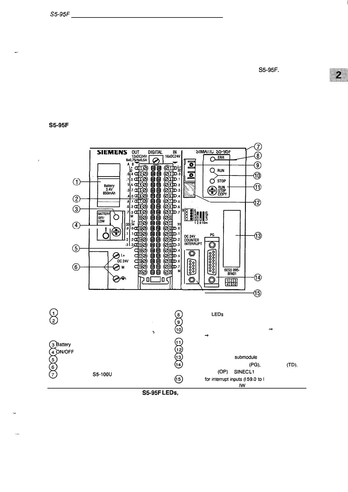
This chapter contains information on the design and principle of operation of the S5-95F.
2.1
Basic System Design - without External 1/0s
The following section discusses the basic unit without expansions. The basic unit has inputs and
outputs available on board.
S5-95F Basic Unit
(4’J
1
1
I
.
k
I
1:1
i“Ak
IFFE
9
RUN
10
STOP
@
RUN
STOP
11
cow
EWA0234S
\
@
8
1
Battery compartment
8
8 Yellow error
LEDs
2 Front connectors for digital inputs
9 Connector for fiber optic cable
(1 32.0 to I 33.7) and
for digital outputs (Q 32.0 to Q 32.7; Q 33.0 to
IO Displays for operating mode: green LED
+
RUN;
Q 33.3 or Q 34.o to Q 34.3)
red LED
+
STOP
I
3 Battety failure display
i
11 Operating mode selector switch
4
OIWOFF
switch
12 DIP switch for subunit identification
5 LED display for digital inputs and outputs
13 Receptacle for memory
submodule
6 Power supply terminals
14 Serial interface for programmer
(PG),
text display
(TD),
7 Connector for
S5-IOOU
bus units
operator panel
(OP)
or SINEC
L1
LAN
(not visible)
~
Interface
forinterruptinputs(l
59.Otol 59.3) and
for counter inputs (IW 36,
IW 38)
.
—
EWA 4NEB 8126210-02
Figure 2-1.
S5-95F
LEDs,
Controls and Interfaces
2-1