Guidelines for the Planning and Installation of the Product S5-95F
3.2 Installation of Programmable Controllers in Accordance with
Principles of EMC
Interference-Free Installation of the S5-95F
What Does EMC Mean?
Electromagnetic compatibility (EMC) is understood to mean the capability of electrical equipment to
operate correctly in a defined electromagnetic environment, without being affected by the
environment and without affecting the environment to an unacceptable degree.
All SIMATIC S5 products have been developed for applications in harsh industrial environments and
meet high requirements for EMC. Before installing the control system, however, you should still
carry out EMC planning and involve possible interference sources in the assessment.
Described in the following section are:
• The various paths over which interference can be picked up in the PLC
• Typical interference sources and their coupling mechanisms
• Basic rules for ensuring EMC.
3.2.1 Overview of Possible Interference
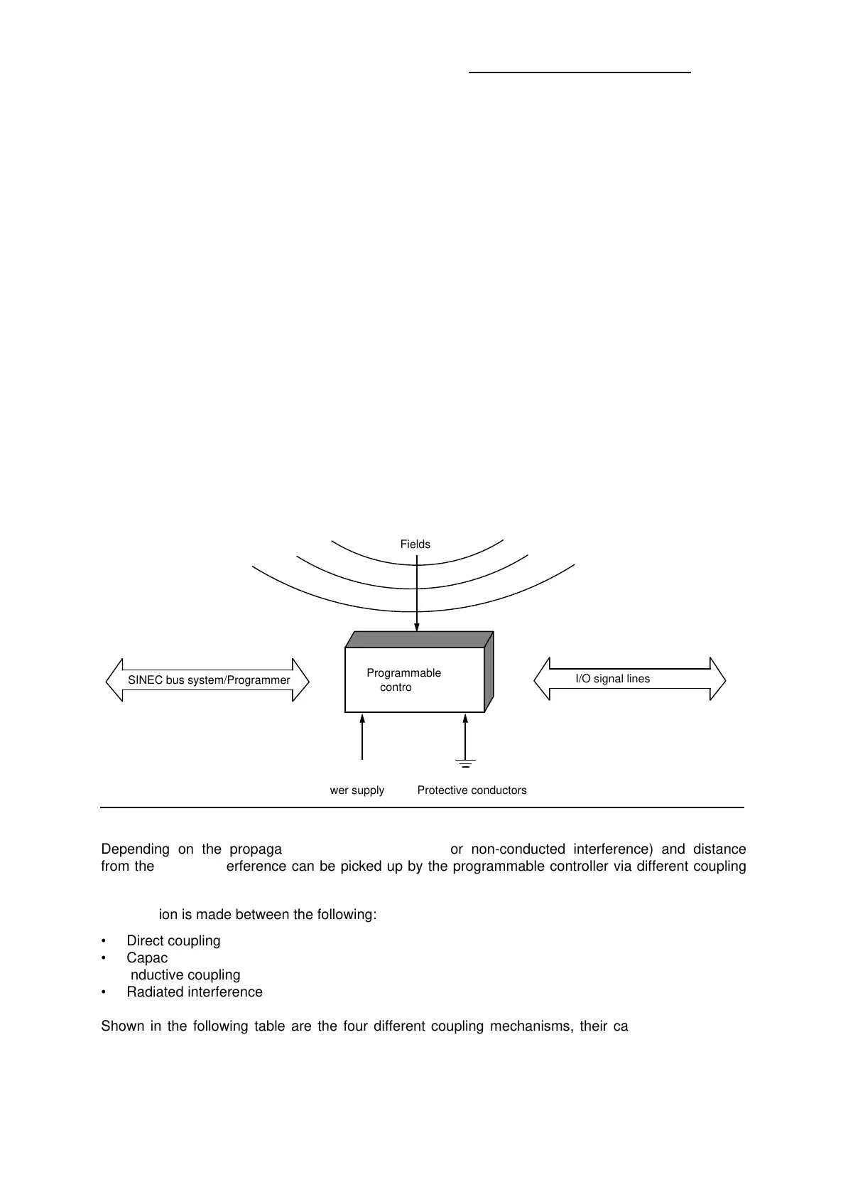
Electromagnetic interference can be picked up by the programmable controller over different paths
(see Figure 3-1).
Figure 3-1. Electromagnetic Interference with Programmable Controllers
a
a
a
a
a
a
a
a
Fields
a
a
a
a
a
a
a
a
a
a
a
a
a
a
a
a
a
a
a
a
a
a
a
a
a
a
a
a
a
a
a
a
a
a
a
a
a
a
a
a
a
a
a
a
a
a
a
a
a
a
a
a
a
a
a
a
a
a
a
a
Programmable
controller
a
a
a
a
a
a
a
a
a
a
a
a
a
a
a
a
a
a
a
a
a
a
Power supply
a
a
a
a
a
a
a
a
a
a
a
a
a
a
a
a
a
a
a
a
a
a
a
a
a
a
a
a
a
a
a
a
a
a
a
a
Protective conductors
a
a
a
a
a
a
a
a
a
a
a
a
a
a
a
a
a
a
a
a
a
a
a
a
I/O signal lines
a
a
a
a
a
a
a
a
a
a
a
a
a
a
a
a
a
a
a
a
a
a
a
a
a
a
a
a
a
a
a
a
a
a
a
a
a
a
a
a
a
a
a
a
a
a
a
a
a
a
a
a
a
a
a
a
a
a
a
a
a
a
a
a
a
a
a
a
a
a
a
a
a
a
a
a
a
a
a
a
a
a
a
a
a
a
a
a
a
a
a
a
a
a
a
a
a
a
a
a
a
a
a
a
a
a
a
a
a
a
a
a
a
a
a
a
a
a
SINEC bus system/Programmer
Depending on the propagation medium (conducted or non-conducted interference) and distance
from the source, interference can be picked up by the programmable controller via different coupling
mechanisms.
A distinction is made between the following:
• Direct coupling
• Capacitive coupling
• Inductive coupling
• Radiated interference
Shown in the following table are the four different coupling mechanisms, their causes and possible
interference sources.
3-2
EWA 4NEB 812 6210-02