Representation of the analog values of analog modules
5.5 Conversion and cycle times of analog modules
S7-300 Automation System Module data
Manual, 08/2006, A5E00105505-04
5-27
5.5 5.5 Conversion and cycle times of analog modules
Conversion time of analog input channels
The conversion time is the total of the basic conversion time plus additional processing times
of the module for:
● Resistance measurement
● Wirebreak monitoring
The basic conversion time depends directly on the conversion method of the analog input
channel (integrating method, actual value conversion.)
The integration time of integrating conversions has a direct influence on conversion times.
The integration time depends on the interference frequency suppression you set in
STEP 7
.
For information on basic conversion times and additional processing times of the various
analog modules, refer to the technical data of the relevant module.
Cycle time of analog input channels
Analog-to-digital conversion, and the transfer of digitized measured values to memory and/or
to the backplane bus, are carried out sequentially, i.e. the analog input channels are
converted in successive order. The cycle time, i.e. the time expiring until an analog input
value is converted again, represents the accumulated conversion time of all activated analog
input channels of the analog input module.
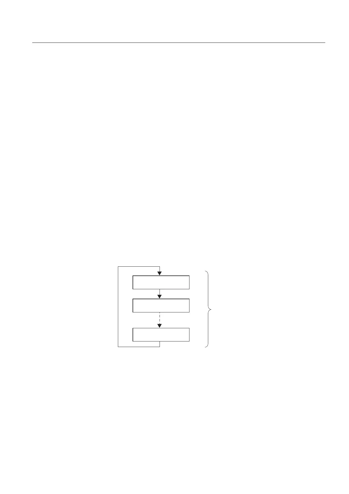
The figure below provides an overview of the cycle time elements for an n-channel analog
module.
&RQYHUVLRQWLPH
FKDQQHO
&RQYHUVLRQWLPH
FKDQQHO
6FDQWLPH
&RQYHUVLRQWLPH
FKDQQHOQ
Figure 5-4 Cycle time of an analog input or output module
Conversion and cycle times for analog input channels in channel groups
Make allowances for the accumulated channel conversion time when the analog input
channels are joined to form channel groups.