EasyManuals Logo

Siemens SIMATIC S7-300 Module data User Manual

Siemens SIMATIC S7-300 Module data
594 pages
To Next Page IconTo Next Page
To Previous Page IconTo Previous Page
Page #467 background imageLoading...
Page #467 background image
Diagnostics data of signal modules
B.3 Channel -specific diagnostics data, starting at byte 8
S7-300 Automation System Module data
Manual, 08/2006, A5E00105505-04
B-5
B.3 B.3 Channel-specific diagnostics data, starting at byte 8
Introduction
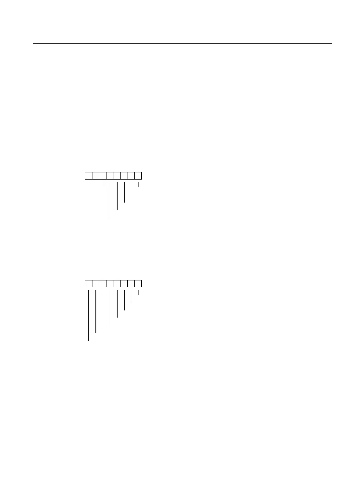
Data record 1 contains the channel-specific diagnostic data, starting at bytes 8 to 15. The
figures below show the assignment of the diagnostics byte of a module-specific channel or
channel group. General rule: An error is indicated by a logic "1" at the relevant bit.
For information on possible error causes and troubleshooting routines, refer to the chapter
"Module diagnostics."
Digital input channel of SM 321; DI 16 x DC 24 V; with hardware/diagnostics interrupts



&RQILJXULQJSDUDPHWHUDVVLJQPHQWHUURU
*URXQGIDXOW
6KRUWFLUFXLWWR/
6KRUWFLUFXLWWR0
:LUHEUHDN
6HQVRUVXSSO\PLVVLQJ
Figure B-4 Diagnostics byte for a digital input channel of SM 321; DI 16 x DC 24 V
Digital output channel of SM 322; DO 8 x DC 24 V/0.5 A; with diagnostics interrupt


&RQILJXULQJSDUDPHWHUDVVLJQPHQWHUURU
*URXQGIDXOW
6KRUWFLUFXLWWR/
6KRUWFLUFXLWWR0
:LUHEUHDN
([WHUQDODX[LOLDU\VXSSO\PLVVLQJ
2YHUWHPSHUDWXUH
Figure B-5 Diagnostics byte for a digital output channel of SM 322; DO 8 x DC 24 V/0.5 A

Table of Contents

Other manuals for Siemens SIMATIC S7-300 Module data

Questions and Answers:

Question and Answer IconNeed help?

Do you have a question about the Siemens SIMATIC S7-300 Module data and is the answer not in the manual?

Siemens SIMATIC S7-300 Module data Specifications

General IconGeneral
SeriesS7-300
ManufacturerSiemens
Protection ClassIP20
SystemSIMATIC S7-300
Digital InputsVaries by module
Digital OutputsVaries by module
Analog InputsVaries by module
Analog OutputsVaries by module
Central Processing UnitVaries by CPU model
Supply Voltage24V DC or 120/230V AC
CPU TypeVaries (e.g., CPU 312, CPU 315, etc.)
MemoryVaries by CPU model
Communication InterfacesMPI, PROFIBUS
Programming LanguagesLAD, FBD, STL, SCL, GRAPH
Operating Temperature0°C to 60°C
Storage Temperature-40°C to 70°C
Relative Humidity10% to 95% (non-condensing)

Related product manuals