Digital modules
3.3 Programming digital modules
S7-300 Automation System Module data
3-8 Manual, 08/2006, A5E00105505-04
3.3 3.3 Programming digital modules
Introduction
Digital modules may have different properties. You can program the properties of certain
modules.
All information in this chapter applies only to programmable digital modules:
● Digital input module SM 321; DI 16 x DC 24 V, with hardware and diagnostic interrupts,
isochronous; (6ES7321-7BH01-0AB0)
● Digital output module SM 322; DO 8 x DC 24 V/0.5 A, with diagnostic interrupt;
(6ES7322-8BF00-0AB0)
● Digital output module SM 322; DO 8 x AC120/230 V /2A ISOL (6ES7322-5FF00-0AB0)
● Relay output module SM 322; DO 8 x Rel. AC230V /5A (6ES7322-5HF00-0AB0)
● Digital IO module SM 327; DI 8/DX 8 x DC 24 V/0.5 A (6ES7327-1BH00-0AB0)
Programming tools
Only program the digital modules in STEP 7 while the CPU is in STOP.
After you defined all parameters, download these from your PG to the CPU. During its STOP
→ RUN transition, the CPU transfers the parameters to the relevant digital modules.
Static and dynamic parameters
Parameters are organized by static and dynamic properties.
Set the static parameters while the CPU is in STOP, as described earlier.
You may also edit dynamic parameters in the active user program of an S7 PLC using SFCs.
However, the parameters set in STEP 7 will be applied again after a RUN → STOP, STOP →
RUN transition of the CPU. The appendix
Parameter sets of the signal modules
describes
the assignment of module parameters in the user program.
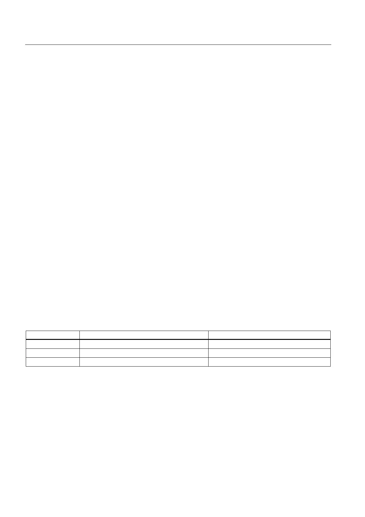
Parameters configurable using CPU operating state
static PG (STEP 7 HW CONFIG) STOP
dynamic PG (STEP 7 HW CONFIG) STOP
SFC 55 in the user program RUN
Parameters of digital modules
The configurable parameters are described in the specific module chapter.
See also
Parameters of digital input modules (Page A-2)