EasyManuals Logo

Siemens SIMATIC S7-300 Module data User Manual

Siemens SIMATIC S7-300 Module data
594 pages
To Next Page IconTo Next Page
To Previous Page IconTo Previous Page
Page #423 background imageLoading...
Page #423 background image
Parameter sets of signal modules
A.2 Parameters of digital input modules
S7-300 Automation System Module data
Manual, 08/2006, A5E00105505-04
A-3
Note
To enable diagnostic interrupts in the user program at data record 1, you first need to enable
diagnostics at data record 0 in
STEP 7
.
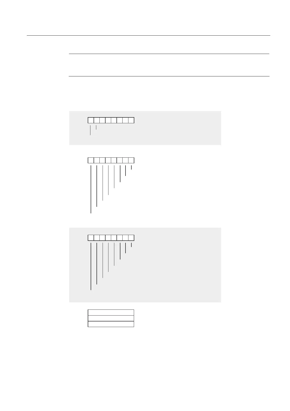
Structure of data record 1
The figure below shows the structure of data record 1 for the parameters of digital input
modules.
You enable a parameter by setting a logical "1" at the corresponding bit.

 
 
+DUGZDUHLQWHUUXSW
+DUGZDUHLQWHUUXSW
RQULVLQJHGJHDWFKDQQHOJURXS
RQIDOOLQJHGJHDWFKDQQHOJURXS
RQULVLQJHGJHDWFKDQQHOJURXS
RQIDOOLQJHGJHDWFKDQQHOJURXS
RQULVLQJHGJHDWFKDQQHOJURXS
RQIDOOLQJHGJHDWFKDQQHOJURXS
RQULVLQJHGJHDWFKDQQHOJURXS
RQIDOOLQJHGJHDWFKDQQHOJURXS
RQULVLQJHGJHDWFKDQQHOJURXS
RQIDOOLQJHGJHDWFKDQQHOJURXS
RQULVLQJHGJHDWFKDQQHOJURXS
RQIDOOLQJHGJHDWFKDQQHOJURXS
RQULVLQJHGJHDWFKDQQHOJURXS
RQIDOOLQJHGJHDWFKDQQHOJURXS
RQULVLQJHGJHDWFKDQQHOJURXS
RQIDOOLQJHGJHDWFKDQQHOJURXS
QRWUHOHYDQW
QRWUHOHYDQW
QRWUHOHYDQW
'LDJQRVWLFVLQWHUUXSWHQDEOH
+DUGZDUHLQWHUUXSWHQDEOH
%\WH
%\WH
%\WH
%\WH
%\WH
%\WH
Figure A-1 Data record 1 for parameters of digital input modules
See also
Diagnostics of digital modules (Page 3-9)

Table of Contents

Other manuals for Siemens SIMATIC S7-300 Module data

Questions and Answers:

Question and Answer IconNeed help?

Do you have a question about the Siemens SIMATIC S7-300 Module data and is the answer not in the manual?

Siemens SIMATIC S7-300 Module data Specifications

General IconGeneral
SeriesS7-300
ManufacturerSiemens
Protection ClassIP20
SystemSIMATIC S7-300
Digital InputsVaries by module
Digital OutputsVaries by module
Analog InputsVaries by module
Analog OutputsVaries by module
Central Processing UnitVaries by CPU model
Supply Voltage24V DC or 120/230V AC
CPU TypeVaries (e.g., CPU 312, CPU 315, etc.)
MemoryVaries by CPU model
Communication InterfacesMPI, PROFIBUS
Programming LanguagesLAD, FBD, STL, SCL, GRAPH
Operating Temperature0°C to 60°C
Storage Temperature-40°C to 70°C
Relative Humidity10% to 95% (non-condensing)

Related product manuals