Digital modules
3.10 Digital input module SM 321; DI 16 x 24 VDC; with hardware and diagnostic interrupts
S7-300 Automation System Module data
3-30 Manual, 08/2006, A5E00105505-04
Causes of error and troubleshooting
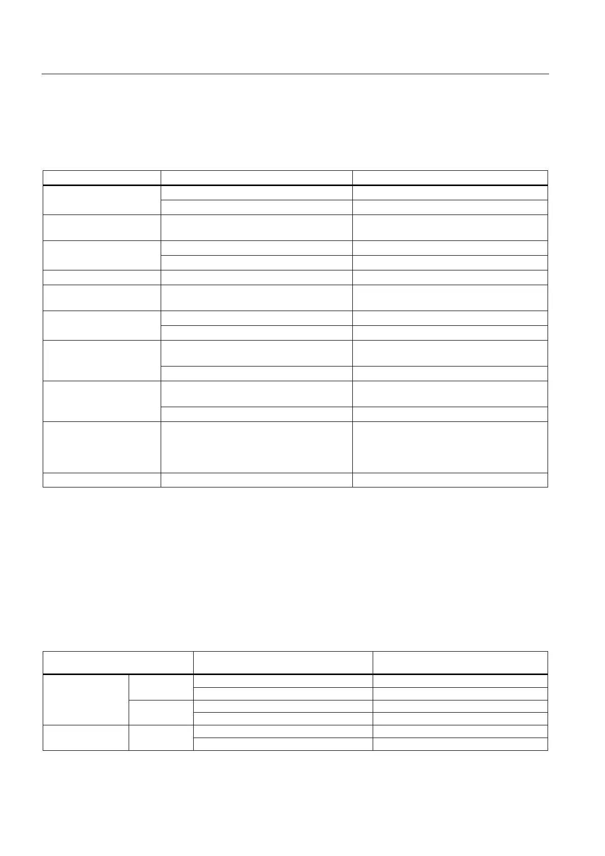
Table 3-12 Diagnostic Messages of the SM 321; DI 16 x DC 24 V, causes of error and troubleshooting
Diagnostics message Possible cause of error To correct or avoid error
Overload at encoder supply Eliminate overload Encoder supply missing
Short-circuit to M at encoder supply Eliminate the short-circuit
External auxiliary voltage
missing
Power supply L+ to module missing Feed supply L+
Power supply L+ to module missing Feed supply L+ Internal auxiliary voltage
missing
Fuse blown in module Replace the module
Fuse blown Fuse blown in module Replace the module
Incorrect module
parameters
Implausible parameter or combination thereof Program the module
Infrequent high electromagnetic interference Eliminate interference Watchdog time-out
Module defective Replace the module
Infrequent high electromagnetic interference Eliminate interference and cycle the power
supply of CPU off/on.
EPROM error
Module defective Replace the module
Infrequent high electromagnetic interference Eliminate interference and cycle the power
supply of CPU off/on.
RAM error
Module defective Replace the module
Hardware interrupt lost The module can not output an interrupt,
because the previous interrupt was not
acknowledged; possibly a configuration error
Change interrupt processing in the CPU, and
reprogram the module as required
The error persists until the module is assigned
new parameters
Module not programmed Startup error Program the module
3.10.4 Reactions of SM 321; DI 16 x DC 24 V
Influence of the operating state and supply voltage on input values
The SM 321; DI 16 x DC 24 input values are determined by the CPU's operating state and
the module's power supply.
Table 3-13 Dependency of input values on the CPU's operating state, and on the L+ power supply of SM 321; DI 16 x
DC 24 V
CPU operating state Power supply L+ at digital module input value
of the digital module
L+ present Process value RUN
L+ missing 0 signal
L+ present Process value
POWER ON
STOP
L+ missing 0 signal
L+ present - POWER OFF -
L+ missing -
(6ES7321-7BH01-0AB0)