Analog modules
6.3 Analog input module SM 331; AI 8 x 16 Bit; (6ES7331-7NF00-0AB0)
S7-300 Automation System Module data
Manual, 08/2006, A5E00105505-04
6-9
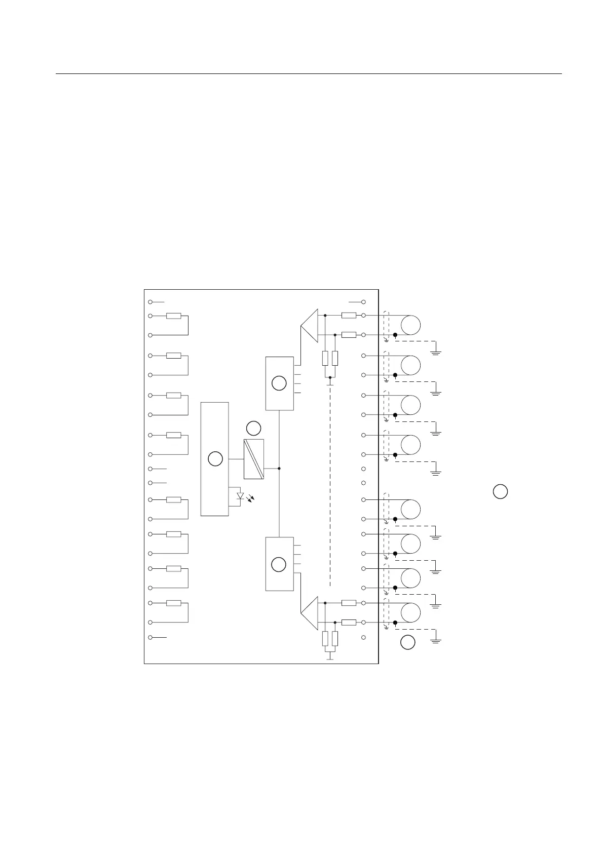
Terminal assignment
The following diagrams show different possible forms of wiring
Wiring: Voltage and current measurement
For current measurements, wire the channel's voltage inputs with relevant current measuring
resistor in parallel. Do so by bridging the channel's input terminals to the adjacent terminals
of the connector.
Example: Set up channel 0 for current measurements by bridging terminals 22 and 2, and
terminals 23 to 3.
At the channel configured for current measurements, connect the current measuring resistor
to the adjacent channel terminals in order to achieve the specified accuracy.
വ
&+
വ
വ
വ
വ
വ
വ
വ
9
9
9
9
9
9
9
6)
ದ
&+
ದ
&+
ದ
&+
ದ
&+
ದ
&+
ದ
&+
ದ
&+
9
ದ
Figure 6-1 Wiring and block diagrams
① Voltage measurement
② Backplane bus interface
③ Electrical isolation
④ Analog-to-Digital Converter (ADC)
⑤ Potential compensation