Analog modules
6.6 Analog input module SM 331; AI 8 x 13 Bit;(6ES7331-1KF01-0AB0)
S7-300 Automation System Module data
6-42 Manual, 08/2006, A5E00105505-04
Resistance measurement with 2, 3 and 4-wire connection
8
,
6
ದ
0
0
ದ
8
,
6
ದ
0
0
ದ
8
,
6
ದ
0
0
ದ
8
,
6
ದ
0
0
ದ
&+
&+
&+
&+
8
,
6
ದ
0
0
ದ
8
,
6
ದ
0
0
ದ
8
,
6
ದ
0
0
ದ
8
,
6
ದ
0
0
ದ
&+
&+
&+
&+
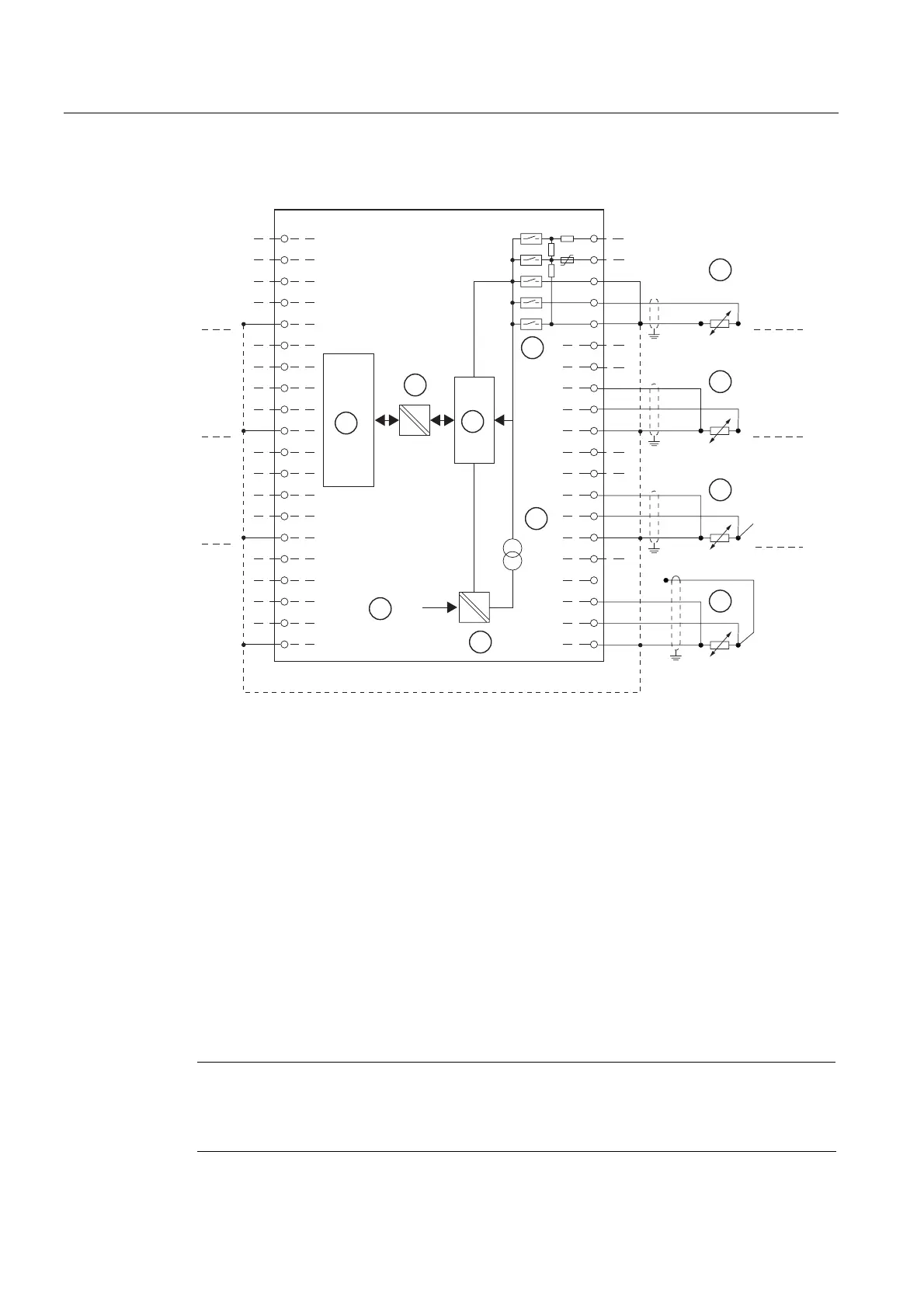
Figure 6-13 Block diagram and wiring diagram
① 2-wire connection. A bridge must be produced between M and S (without line resistance
compensation).
② 3-wire connection
③ 4-wire connection. The fourth line must not be wired (line remains unused)
④ 4-wire connection. The fourth line is routed to the terminal strip in the cabinet but is not wired.
⑤ Internal supply
⑥ + 5V from backplane bus
⑦ Logic and backplane bus interface
⑧ Electrical isolation
⑨ Multiplexer
⑩ Analog to Digital Converter (ADC)
⑪ Source of current
Note
It is not necessary to interconnect the M- terminals when measuring resistances and
resistance thermometers. A connection between the M- terminals can however increase the
interference resistance.