Dimensional drawings
C.2 Dimensional drawings of the power supply modules
S7-300 Automation System Module data
Manual, 08/2006, A5E00105505-04
C-9
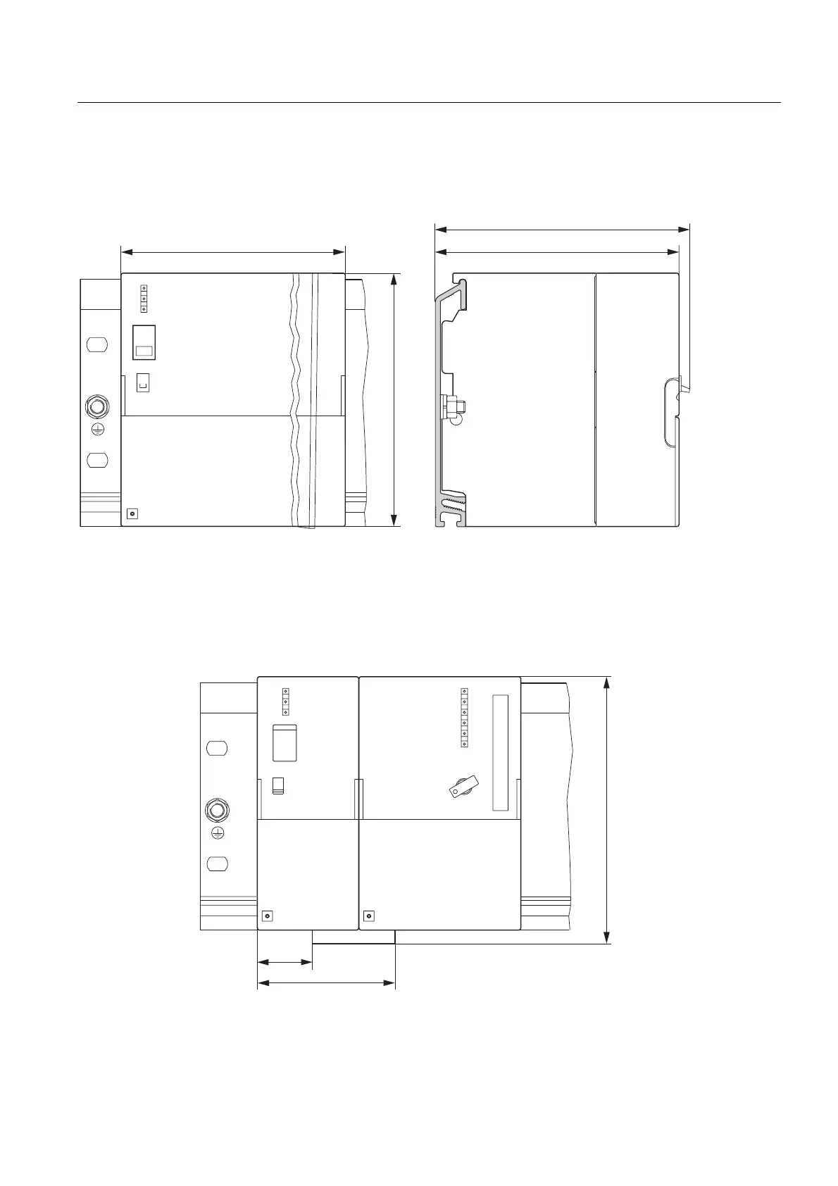
PS 307; 10 A
The figure below shows the dimensional drawing of the PS 307; 10 A power supply module.
Figure C-12 Power supply module PS 307; 10 A
PS 307; 5 A with 313/314/315/ 315-2 DP CPU
The figures below show the dimensional drawings of a configuration consisting of a power
supply module PS 307; 5 A and a 313/314/315/315-2 DP CPU. Observe the dimensions
derived from the use of a power connector when wiring the PS 307; 5 A to the CPU.
Figure C-13 Dimensional drawing of power supply module PS 307; 5 A with CPU 313/314/315/315-2
DP, front view