EasyManuals Logo

Siemens SIMATIC S7-300 Module data User Manual

Siemens SIMATIC S7-300 Module data
594 pages
To Next Page IconTo Next Page
To Previous Page IconTo Previous Page
Page #63 background imageLoading...
Page #63 background image
Digital modules
3.7 Digital output module SM 321; DI 32 x AC 120 V; (6ES7321-1EL00-0AA0)
S7-300 Automation System Module data
Manual, 08/2006, A5E00105505-04
3-15
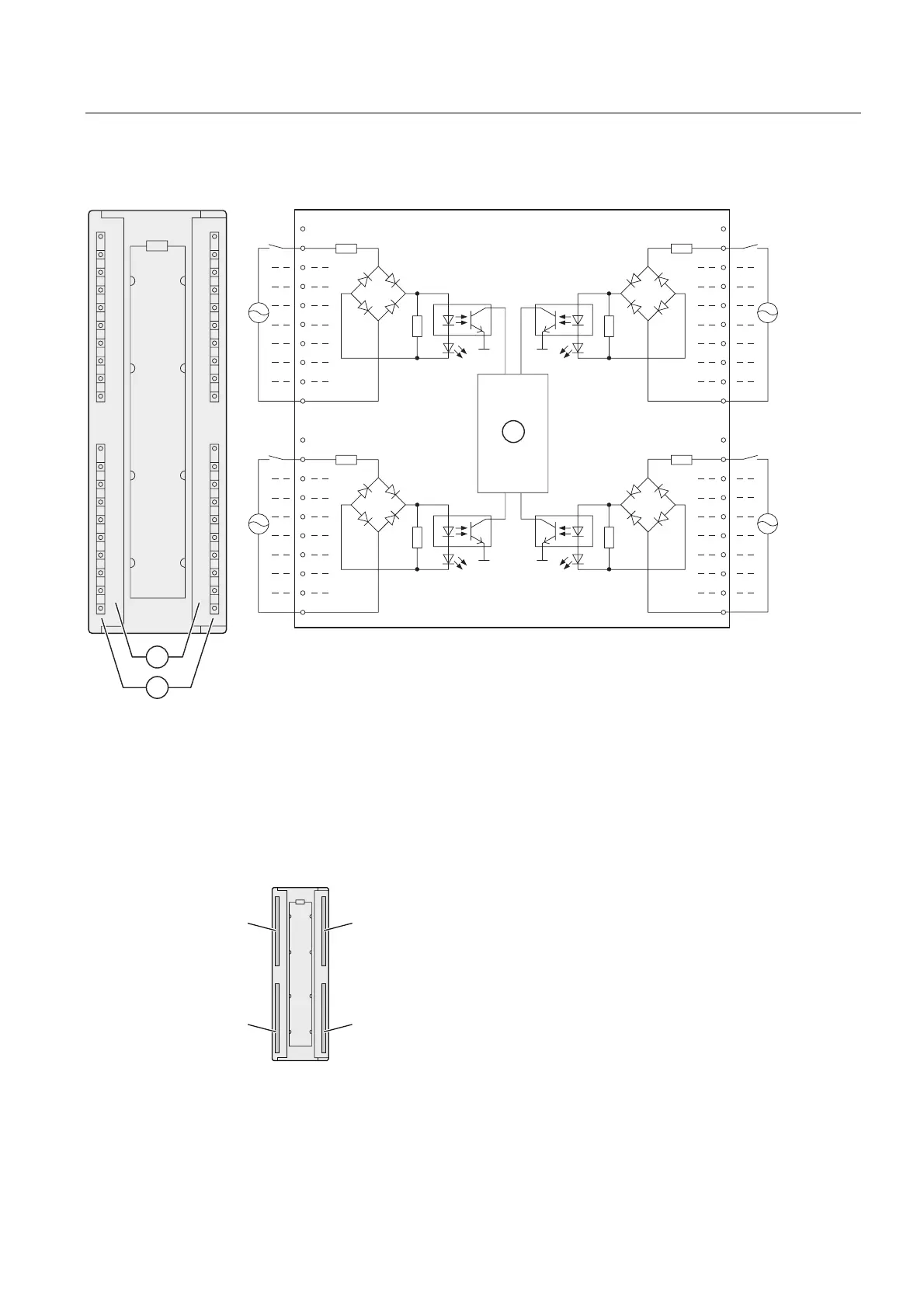
Wiring and block diagrams SM 321; DI 32 x AC 120 V

/
1










/
1










/
1










/
1
Channel number
Status display - green
Backplane bus interface
Terminal assignment
The figure below shows the channel addressing (input byte x up to input byte x +3).
[
[
[
[

Table of Contents

Other manuals for Siemens SIMATIC S7-300 Module data

Questions and Answers:

Question and Answer IconNeed help?

Do you have a question about the Siemens SIMATIC S7-300 Module data and is the answer not in the manual?

Siemens SIMATIC S7-300 Module data Specifications

General IconGeneral
SeriesS7-300
ManufacturerSiemens
Protection ClassIP20
SystemSIMATIC S7-300
Digital InputsVaries by module
Digital OutputsVaries by module
Analog InputsVaries by module
Analog OutputsVaries by module
Central Processing UnitVaries by CPU model
Supply Voltage24V DC or 120/230V AC
CPU TypeVaries (e.g., CPU 312, CPU 315, etc.)
MemoryVaries by CPU model
Communication InterfacesMPI, PROFIBUS
Programming LanguagesLAD, FBD, STL, SCL, GRAPH
Operating Temperature0°C to 60°C
Storage Temperature-40°C to 70°C
Relative Humidity10% to 95% (non-condensing)

Related product manuals