3UF50 compatibility mode
11.2 Diagram of send and receive data
SIMOCODE pro
180 System Manual, 05/2019, A5E40507475002A/RS-AD/004
11.2 Diagram of send and receive data
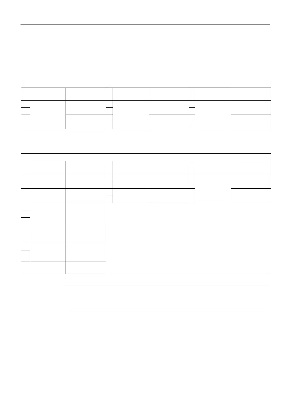
The following table shows the send and receive data in compatibility mode:
Table 11- 1 "Receive" configuration
Basic type 1,
Basic type 1,
Basic type 2,
Basic type 2,
Basic type 3,
Basic type 3,
0 Receive data Cyclic receive
bit 0 to 1.7
0 Receive data Cyclic receive
bit 0 to 1.7
0 Receive data Cyclic receive
bit 0 to 1.7
2 Not supported 2 Not supported 2 Not supported
Table 11- 2 "Send" configuration
Basic type 1,
Basic type 1,
Basic type 2,
Basic type 2,
Basic type 3,
Basic type 3,
Send data Cyclic receive
bit 0 to 1.7
Send data Cyclic receive
bit 0 to 1.7
Send data Cyclic receive
bit 0 to 1.7
Motor current Specified: max.
current I
max
Motor current Specified: max.
current I
max
Acycl. Send
Bit 0 to 1.7
Number of
starts
Specified:
Number of starts
(Byte 0)
Counter 1 value Specified:
Counter 1 -
8
Counter 2 value Specified:
Counter 2 -
10
11 Sensor value Specified: TM -
data bytes 2 - 11 are always permanently assigned in compatibility mode
(see Table "'Send' configuration").