Commissioning, service, troubleshooting
13.3 Service
SIMOCODE pro
System Manual, 05/2019, A5E40507475002A/RS-AD/004
283
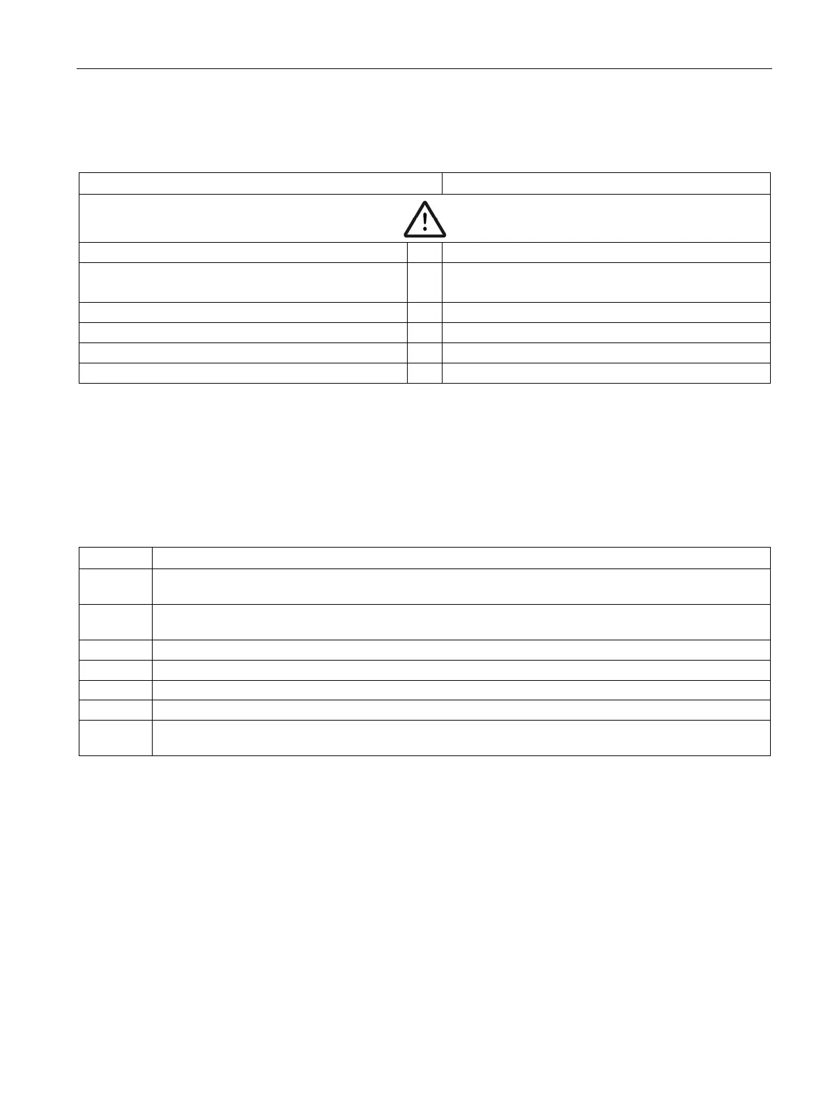
The following table shows which 2nd generation current/voltage measuring module replaces
a 1st generation current/voltage measuring module:
1st generation current/voltage measuring module
2nd generation current/voltage measuring module
e
e
3UF7111-1AA00-0, I
e
= 2.4 to 3 A
3UF7111-1AA00-0, I
e
= 3.0 to 25 A
→
3UF7110-1AA01-0, I
e
= 0.3 to 4 A
3UF7111-1AA01-0, I
e
= 3 to 40 A
e
e
3UF7113-1AA01-0, I
e
= 20 ... 200 A
3UF7113-1AA00-0, I
e
= 20 ... 200 A
e
e
3UF7114-1BA01-0, I
e
= 20 ... 200 A
3UF7114-1BA00-0, I
e
= 20 ... 200 A
13.3.4 Exchanging a 3UF52 operator panel for a 3UF720 operator panel
To exchange a 3UF52 operator panel for the smaller 3UF720 operator panel, proceed as
follows:
Table 13- 23 Exchanging a 3UF52 operator panel for a 3UF720 operator panel
1 Unscrew the four mounting bracket screws and remove the 3UF52 operator panel from the front panel or
2 Ensure that the dimensions of the cutout in the front panel or cabinet door measure 91.5 + 0.5 mm (width)
and 54.5 + 0.5 mm (height) (see figure).
Slide the seal provided onto the operator panel adapter (see figure).
Position the operator panel adapter in the cutout.
Position the operator panel in the adapter.
Snap the four mounting brackets onto the operator panel.
7 Lock the operator panel in position by tightening the four mounting bracket screws
(see figure and safety information!).