Technical data
15.11 Typical reaction times
SIMOCODE pro
System Manual, 05/2019, A5E40507475002A/RS-AD/004
365
15.11 Typical reaction times
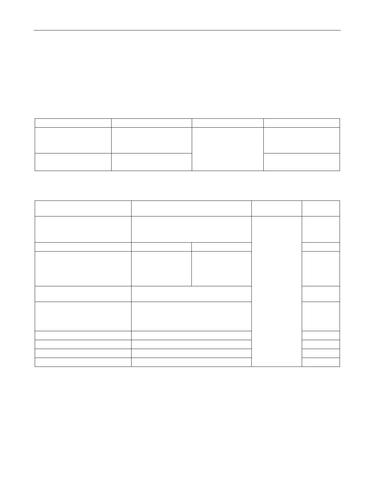
15.11.1 Typical reaction times of the SIMOCODE pro C/V device series
Table 15- 1 Typical reaction times of SIMOCODE pro C device series
Basic unit:
Thermistor:
Set delay time
400 ms
30 ms 10 ms
-
Current measurement:
Internal ground fault:
200 ms
300 ms ... 600 ms + set delay
-
-
Table 15- 2 Typical reaction times of SIMOCODE pro V device series
1)
Basic unit:
Thermistor:
Set delay time
400 ms
5 ms 10 ms
-
2), 4)
Current measurement:
Voltage measurement:
Active power / cos phi:
300 ms
300 ms
1000 ms
3)
200 ms
200 ms
200 ms
3)
-
-
-
Ground-fault module / external
100 ms
3)
-
Digital modules:
• 24 V DC version
• 110 V - 240 V AC/DC version
15 ms + delay time
50 ms + delay time
25 ms
25 ms
DM-F PROFIsafe 15 ms + delay time 30 ms
1) Based upon a typical hardware set-up: Basic unit + current measuring module +
2 expansion modules
Reaction time = inputs conversion time + internal processing time + outputs conversion time