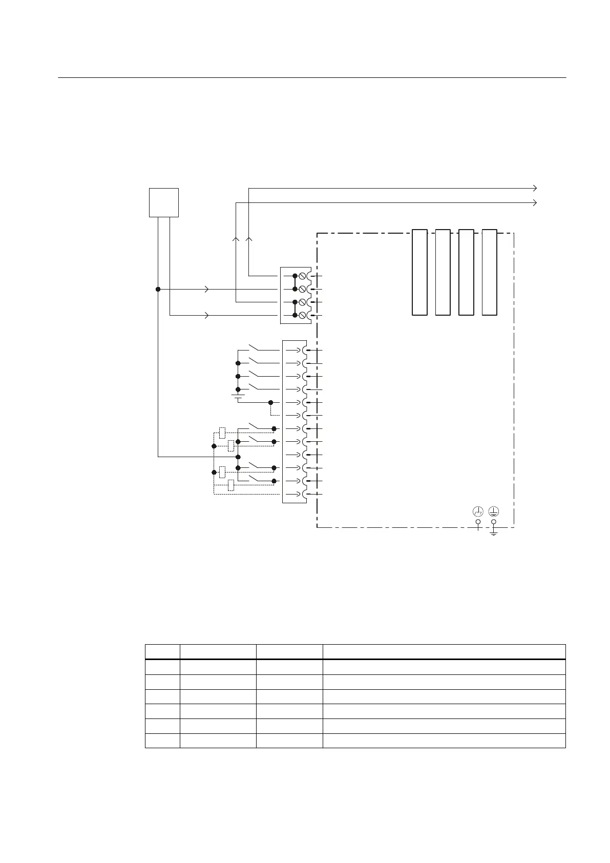
Connection and block diagram
The following figure shows the schematic diagram and the connection of the digital inputs/
outputs on the CX32 and the associated external power supply.
&;FRQWUROOHUH[WHQVLRQ
'5,9(&/L4VRFNHW
'5,9(&/L4VRFNHW
'5,9(&/L4VRFNHW
'5,9(&/L4VRFNHW
-XPSHURSHQHOHFWULFDO
LVRODWLRQIRUGLJLWDOLQSXWV',
&DQEHLQGLYLGXDOO\
SDUDPHWHUL]HGDV
LQSXWRXWSXW
H[W
9
0
0
',
',
',
',
0
0
','2
','2
','2
','2
0
0
9
0
0
0
0
;
;
;;;;
Figure 7-7 CX32 digital inputs/outputs connection diagram
Interface assignment of X122
Table 7-16 Digital inputs/outputs X122
Pin Designation
1)
Signal type
2)
Notes
1 DI 0 I Digital input 0
2 DI 1 I Digital input 1
3 DI 2 I Digital input 2
4 DI 3 I Digital input 3
5 G1 GND Ground for DI0 – DI3 (electrically isolated relative to G)
6 G GND Ground
Supplementary system components
7.4 Controller Extension CX32
SIMOTION D4x5
Manual, 04/2014 99

 Loading...


