3.2 Operator control elements
3.2.1 Service and operating mode switch
Properties of the service and operation mode switch
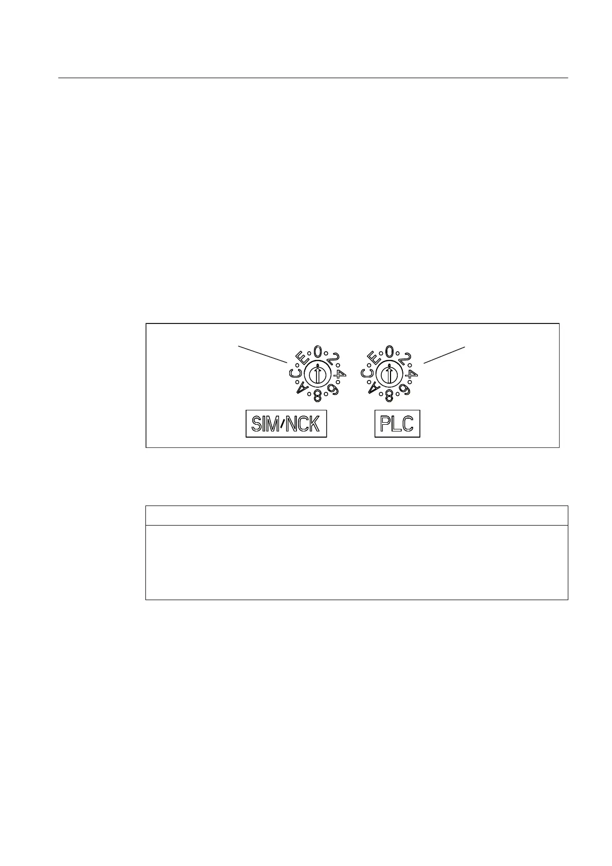
SIMOTION D4x5 has a Service selector switch and a mode switch in the lower section of the
front panel.
The switch on the right labeled PLC is used for switching the operating mode of the
SIMOTION D4x5.
The Service selector switch on the left (labeled SIM/NCK) is for service and diagnosis functions
only. In "normal" operation this switch must remain in the 0 position (see figure below).
0RGHVHOHFWRUVZLWFK
6HUYLFHVHOHFWRU
VZLWFK
Figure 3-4 Mode switch and Service selector switch SIMOTION D4x5
NOTICE
Damage from electrostatic discharge
The rotary switch can be destroyed by static electricity.
Operate the rotary switch only with an insulated screwdriver.
Comply with the ESD rules.
Operator control (hardware)
3.2 Operator control elements
SIMOTION D4x5
Manual, 04/2014 43

 Loading...


