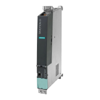
Mode switch
The following table contains the possible mode switch positions and the associated LED
displays.
The mode switch positions are explained in the order in which they are arranged on
the SIMOTION D4x5.
Table 3-1 Mode switch position
Switch position Meaning LED
0 RUN RUN
1 STOPU SU/PF
2 STOP STOP
3 MRES The MRES operating states are indicated via the STOP LED. (ON/
OFF/flashing, see
SIMOTION D4x5
Commissioning and Hardware
Installation Manual)
Other selector positions are not assigned
The following table contains the states of the SIMOTION D4x5 that can be set via the mode
switch.
Table 3-2
Mode switch settings
Meaning Explanations
RUN SIMOTION D4x5 runs the user program and all associated system services:
●
Reading process image of inputs
● Execution of the user programs assigned to the execution system.
● Writing process image of outputs
The technology packages are active in this state. They can execute commands from the
user program.
STOPU SIMOTION D4x5 is not processing a user program.
●
The technology packages are active. Test and commissioning functions can be
executed. The user program is not active.
● The I/O modules are in a secure state. This means, for example, that digital outputs
are "LOW" and analog outputs are de-energized or at zero current.
STOP SIMOTION D4x5 is not processing a user program.
●
It is possible to load a complete user program.
● All system services (communications, etc.) are active.
● The I/O modules are in a secure state. This means, for example, that digital outputs
are "LOW" and analog outputs are de-energized or at zero current.
● The technology packages are inactive, i.e. all enables are deleted. No axis motions
can be executed.
MRES Performing a memory reset on the SIMOTION D4x5/restoring the factory setting
Using
the MRES switch position, you can perform depending on the operating sequence
● SIMOTION D4x5 or
● restore the SIMOTION D4x5 to its factory setting, depending on the operating
sequence.
For further details, see the
SIMOTION D4x5
Commissioning and Hardware
Installation Manual.
Operator control (hardware)
3.2 Operator control elements
SIMOTION D4x5
44 Manual, 04/2014

 Loading...


