7.3.3.5 Analog inputs and outputs
Table 7-7
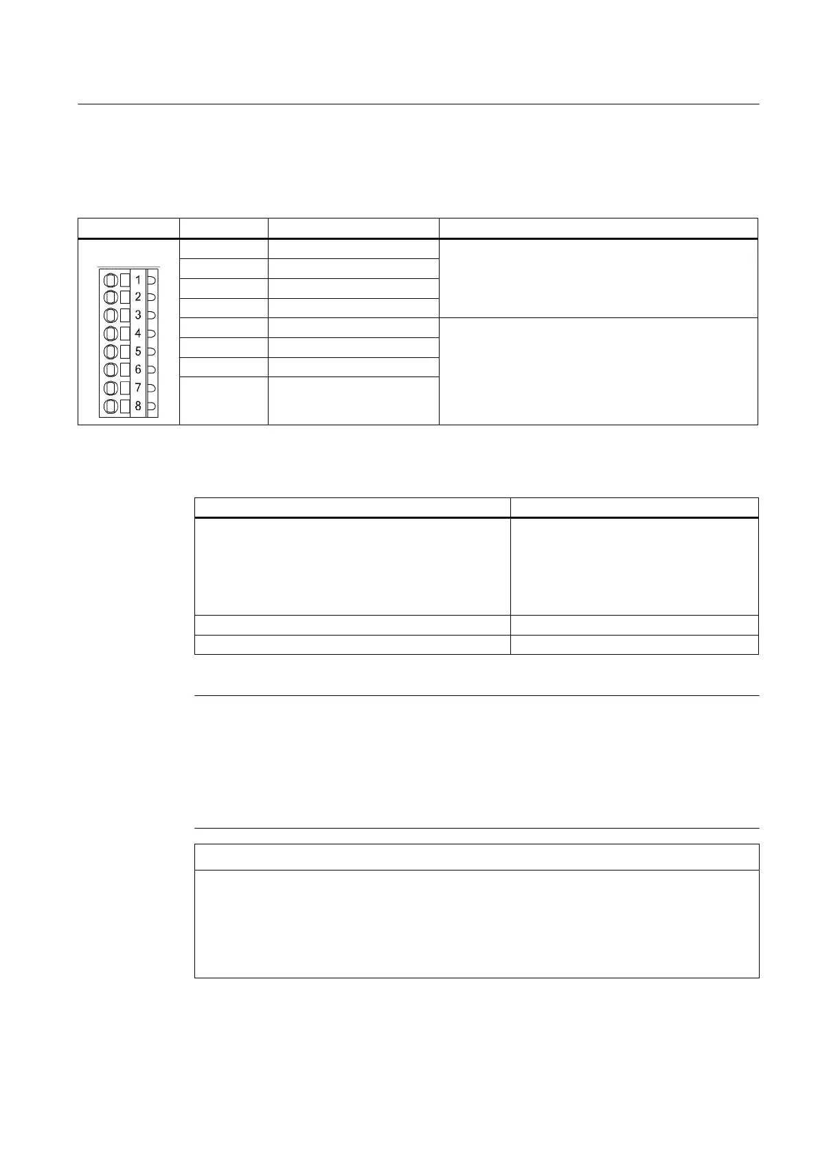
Terminal block X482
Terminal Designation
1)
Technical specifications
1 AI 0+ Analog inputs (AI):
- Voltage: -10 V to +10 V
- Internal resistance: 65 k
Ω
- Resolution: 13 bits + sign
2 AI 0-
3 AI 1+
4 AI 1-
5 AO 0+ Analog outputs (AO):
- Voltage range: -10 V to +10 V
- Load current: Max. -3 mA to +3 mA
- Resolution: 11 bits + sign
- Cont. short-circuit strength
6 AO 0-
7 AO 1+
8 AO 1-
Table 7-8
X482 wiring
Features Type
Connectable cable types
- Rigid
- Flexible
- Flexible, with end sleeve without plastic sleeve
- AWG/kcmil
Conductor cross-sections
0.14 mm
2
to 0.5 mm
2
0.14 mm
2
to 0.5 mm
2
0.25 mm
2
to 0.5 mm
2
26 to 20
Stripped length 8 to 9 mm
Tool Screwdriver 0.4 x 2.0 mm
Note
An open input is interpreted as approximately "0 V."
The power supply of the analog inputs/outputs of the TB30 is via the option slot of the D4x5
Control Unit and not via X424.
The shield is connected to the Control Unit. For more information, see
SIMOTION D4x5
Commissioning and Hardware Installation Manual, Chapter "Connection."
NOTICE
Incorrect results of analog-to-digital conversion due to impermissible input voltage
The common mode range must not be violated.
Makes sure that the analog input voltage signals can have a maximum voltage of ±30 V with
respect to the reference potential. If the range is infringed, incorrect results may occur during
analog/digital conversion.
Supplementary system components
7.3 TB30 terminal board
SIMOTION D4x5
Manual, 04/2014 93

 Loading...


