2 Description of Functions 02.93
2.1.1 Overview
list) for the user-specific displays are stored (e.g. table for the current magazine assignment or
input screen form for tool offsets).
TO memory
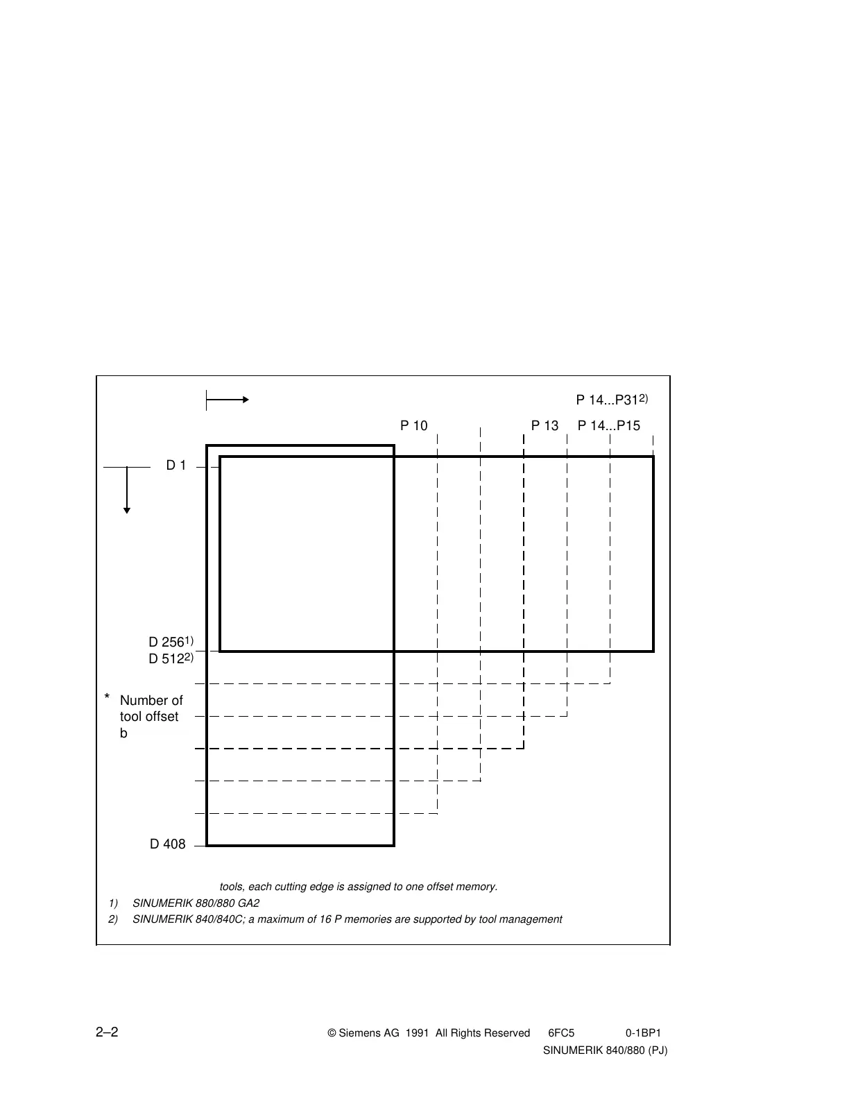
The tool data is kept in the TO memory. For each cutting edge, one tool offset block is stored,
which is addressed by a D number. The TO memory is referenced via the offset addresses (D
Nos.) from package 1 of the PLC.
Configuration of the TO memory
The configuration of the TO memory, and thus the number of the tools to be stored, is variable
within specific limits and depends on the following factors:
• Size of the storage area 16 Kbytes in the case of SINUMERIK 880, 32 Kbytes for
SINUMERIK 840
• Total number of cutting edges of all tools
• Length of the tool offset blocks, i.e. the degree of utilization of the TO memory area
between P10 and P15 (see Figure 2.2).
Fig. 2.2 TO memory configuration
a
a
a
a
a
a
a
a
a
a
a
a
a
a
a
a
a
a
P 10 P 14...P15P 13
*
Number of
tool offset
blocks
P 0
a
a
a
a
a
a
a
a
a
a
a
a
a
a
a
a
a
a
a
a
a
a
a
a
a
a
a
a
a
a
a
a
a
a
a
a
a
a
a
a
a
a
a
a
a
a
a
a
a
a
a
a
a
a
a
a
a
a
a
a
a
a
a
a
a
a
a
a
a
a
a
a
a
a
a
a
a
a
a
a
a
a
a
a
a
a
a
a
a
a
a
a
a
a
a
a
a
a
a
a
a
a
a
a
a
a
a
a
a
a
a
a
a
a
a
a
a
a
a
a
a
a
a
a
a
a
a
a
a
a
a
a
a
a
a
a
a
a
a
a
a
a
a
a
a
a
a
a
a
a
a
a
a
a
a
a
a
a
a
a
a
a
a
a
a
a
a
a
a
a
a
a
a
a
a
a
a
a
a
a
a
a
a
a
a
a
a
a
a
a
a
a
a
a
a
a
a
a
a
a
a
a
a
a
a
a
a
a
a
a
a
a
a
a
a
a
a
a
a
a
a
a
a
a
a
a
a
a
a
a
a
a
a
a
a
a
a
a
Tool data
a
a
a
a
a
a
a
a
a
a
a
a
a
a
a
P 9 P 11 P 12
*) For multiple-edge tools, each cutting edge is assigned to one offset memory.
1) SINUMERIK 880/880 GA2
2) SINUMERIK 840/840C; a maximum of 16 P memories are supported by tool management
a
a
a
a
a
a
a
a
a
a
a
a
a
a
a
a
a
a
a
a
a
a
a
a
a
a
a
a
a
a
a
a
a
a
a
a
a
a
a
a
a
a
a
a
a
a
a
a
a
a
a
a
a
a
D 256
1)
D 512
2)
a
a
a
a
a
a
a
a
a
a
a
a
a
a
a
D 1
a
a
a
a
a
a
a
a
a
a
a
a
a
a
a
a
a
a
a
a
a
D 408
P 14...P31
2)
2–2 © Siemens AG 1991 All Rights Reserved 6FC5 197-0AA40-1BP1
SINUMERIK 840/880 (PJ)

 Loading...


