11.92 2 Description of Functions
2.1 General
2 Description of Functions
2.1 General
2.1.1 Overview
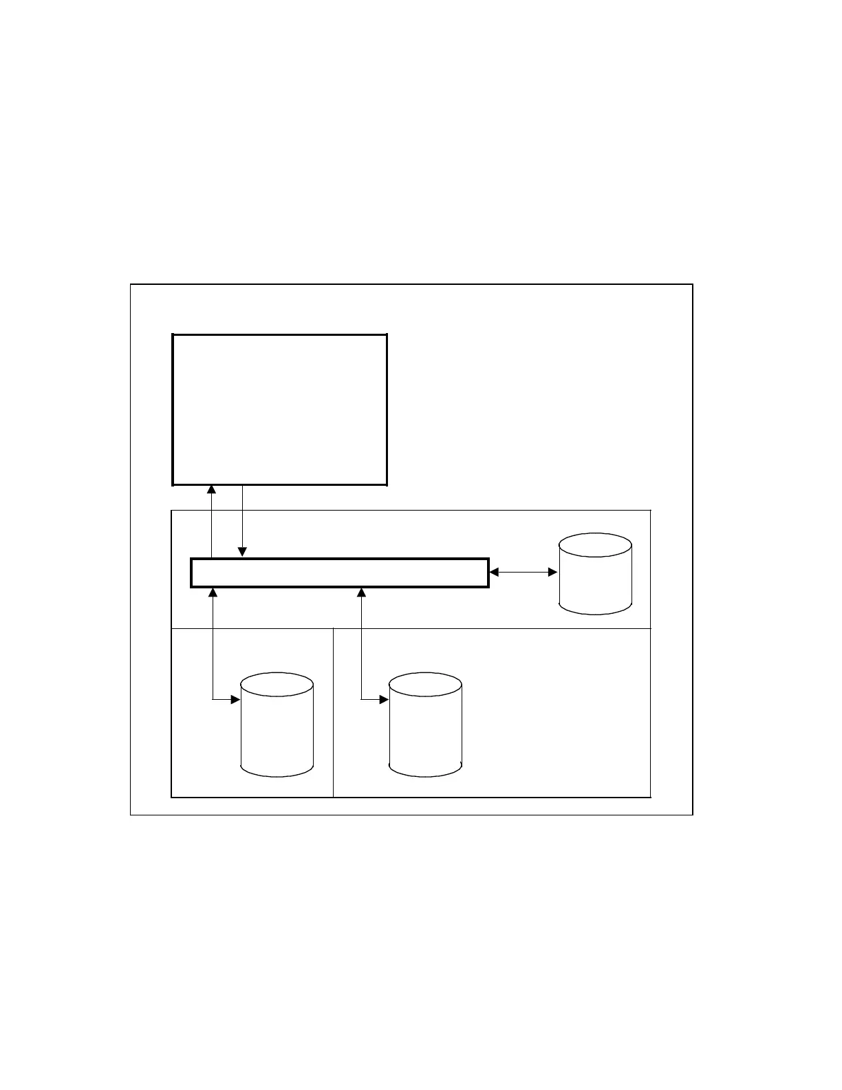
Hardware structure/data structure
The data relating to tool management are divided up as follows in the SINUMERIK 840/880
system:
Fig. 2.1 Distribution of the data required for tool management
Current
magazine
assign-
ment
Display program
Tool offset
PLCNC
COM
UMS
TO DBs
SINUMERIK 880,
SINUMERIK 840 or
SINUMERIK 840C
operator panel
The TO memory is assigned to the NC area; it is physically located in the link RAM. The tool
offsets for the individual cutting edges are stored in the TO memory. The current assignment
of the tool-holding magazine is kept in data blocks in the PLC area. The COM area contains,
amongst other things, the UMS (user memory submodule) where the display descriptions (link
© Siemens AG 1991 All Rights Reserved 6FC5 197-0AA40-1BP1 2–1
SINUMERIK 840/880 (PJ)

 Loading...


