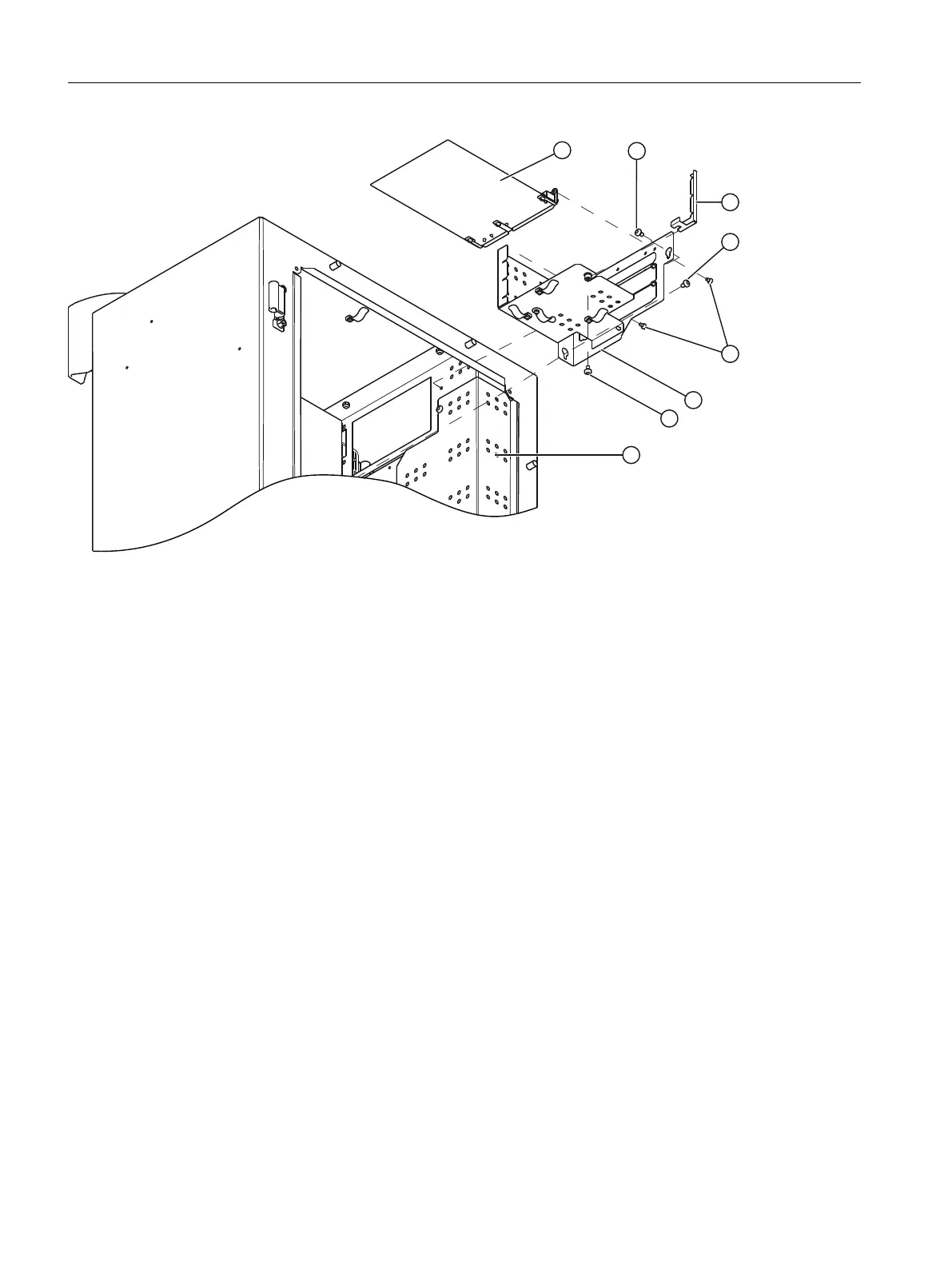
③ Processing unit (PU) ⑯ Screws (2 units)
⑬ Screw ⑰ Electronics base plate
⑭ Printed circuit board holder ⑱ Screw
⑮ Screw ⑲ Shielding plate
Figure11-4 Replacing the processing unit
1. Isolate the device from power.
2. Loosen the six screws and open the door.
3. Loosen the three screws and remove the shield plate ⑲.
4. Pull out the connectors for the following cables depending on the installation situation:
– Power cable ①
– 26-pin ribbon cable to display ④
– 12-pin ribbon cable to analyzer modules AM and option module OM2.2 ②
– 50-pin ribbon cable to option module OM 1.1 ⑤
– 26-pin ribbon cable to the analyzer modules ⑪⑫
– Connecting cable to the terminal block (TB) ⑦⑧⑨
5. Loosen the screws ⑮ and ⑱. Remove the electronics base plate ⑰.
6. Loosen the screw ⑬ and remove the printed circuit board holder ⑭.
7. Loosen the two screws ⑯ and remove the processing unit ③.
Maintenance and servicing
11.7Replacing the processing module
Wall-mounted device
150 Operating Instructions, 07/2023, A5E31930403-AB

 Loading...


