Preparing for installation
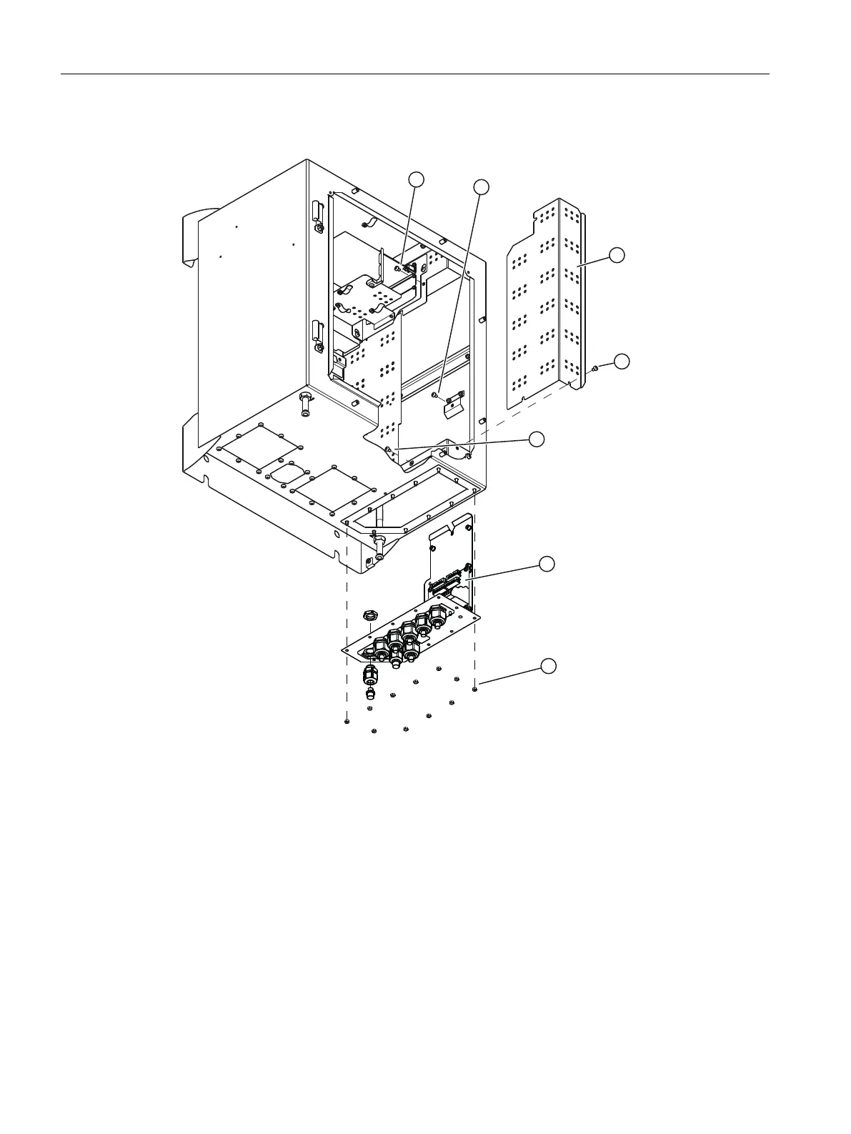
① Screw shield plate ④
⑤
Screw shield plate
② Screw, cable gland plate ⑥ "Standard" terminal block on the cable
gland plate
③ Shielding plate signal lines ⑦ Hexagon nuts (11 units)
Figure7-15 Removing the cable gland plate
1. Isolate the device from power.
2. Loosen the six screws and open the door.
3. Loosen the three screws ①, ④ and ⑤ and remove the shield plate for signal cables ③.
4. Loosen the screw ② on the inside of the right side panel and the eleven hex nuts ⑦ at the
bottom of the housing.
5. Remove the cable gland plate including the "Standard" terminal block ⑥.
Installing / removing and connecting analyzer and option modules
7.11Installing option modules
Wall-mounted device
86 Operating Instructions, 07/2023, A5E31930403-AB

 Loading...


