Procedure
1. Connect the option modules as follows after installation:
– OM1.1 to the processing unit using the 50-pin ribbon cable
– OM 2.x: Use the following cables to connect the OM2.x:
Option
module
Cables
OM 2.1 26-pin ribbon cable with the analyzer module PCB(s)
OM 2.2 26-pin ribbon cable with the analyzer module PCB(s) and via the 12-pin ribbon
cable (CAN BUS) with the processing module
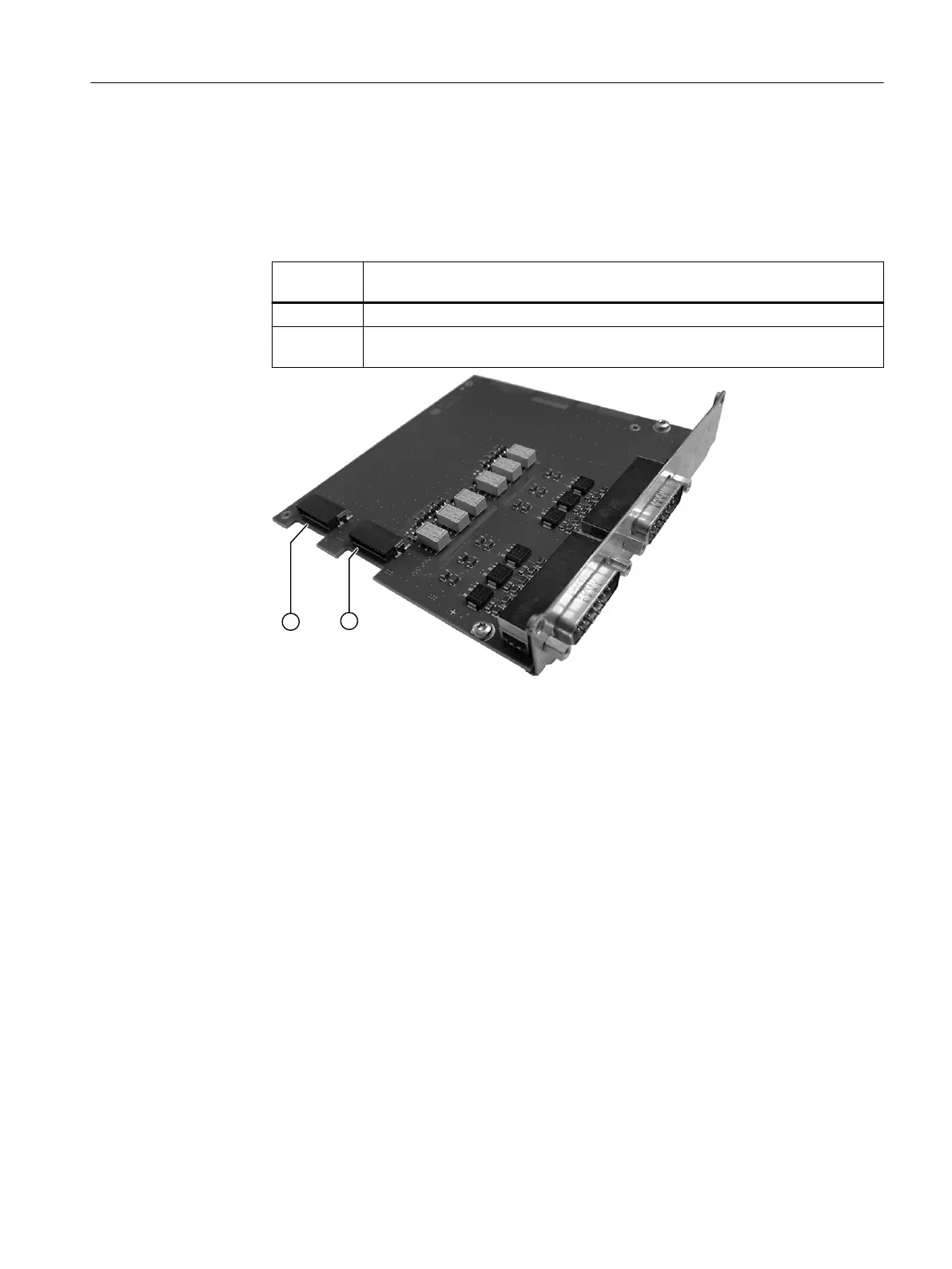
① Connection of the 26-pin ribbon cable to the AM1
② Connection of the 26-pin ribbon cable to the AM2
Figure7-18 Position of the connector sockets based on example of OM2.1
2. Connect the option modules with the corresponding terminal block:
Installing / removing and connecting analyzer and option modules
7.12Wiring option modules
Wall-mounted device
Operating Instructions, 07/2023, A5E31930403-AB 89

 Loading...


