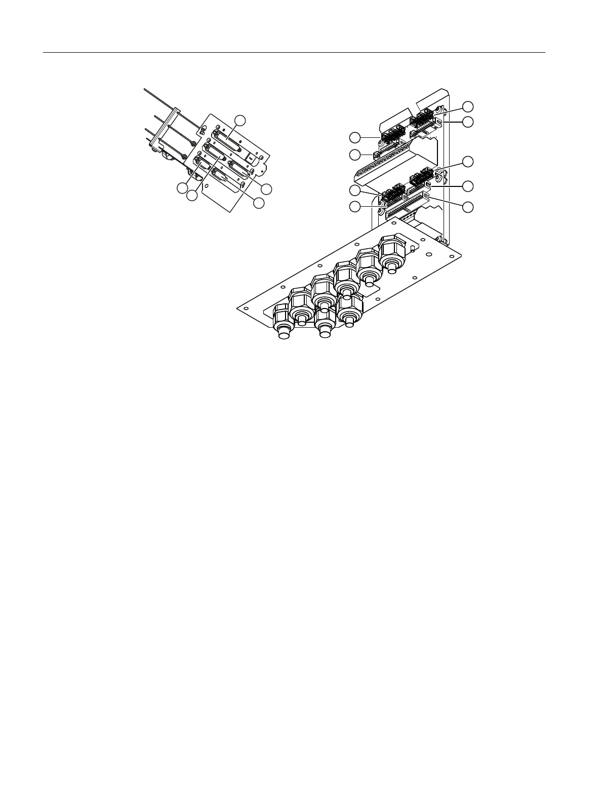
Figure7-19 Assignment of the option modules to the terminal blocks
– OM 1.1 using the 25-pin connecting cable OM1.1 - TB:
④ ↔ ⑫ or ⑥ ↔ ⑮
– OM 2.1 using the 15-pin connecting cable OM 2.1 - TB:
⑤ ↔ ⑨ or ⑦ ↔ ⑩
– OM 2.2 using the 15-pin connecting cable OM 2.2 - TB:
⑤ ↔ ⑬ or ⑦ ↔ ⑯
The processing unit is connected to the "Standard" terminal block (connecting cable PU -
TB ③ ↔ ⑧).
The terminal blocks are connected with each other by means of the connecting cables TB -
TB (⑨ ↔ ⑪ or ⑩ ↔ ⑭).
3. Mount the shield plate for signal cables.
Tighten the three screws with a torque of 2.0Nm.
4. Close the door and fasten the six Torx screws.
Tighten the screws with a torque of 3.5Nm.
Installing / removing and connecting analyzer and option modules
7.12Wiring option modules
Wall-mounted device
90 Operating Instructions, 07/2023, A5E31930403-AB

 Loading...


