2.3 Power swing detection (optional)
111
7SA522 Manual
C53000-G1176-C155-3
bility. For release of the power swing detection a further criterion is therefore used. In
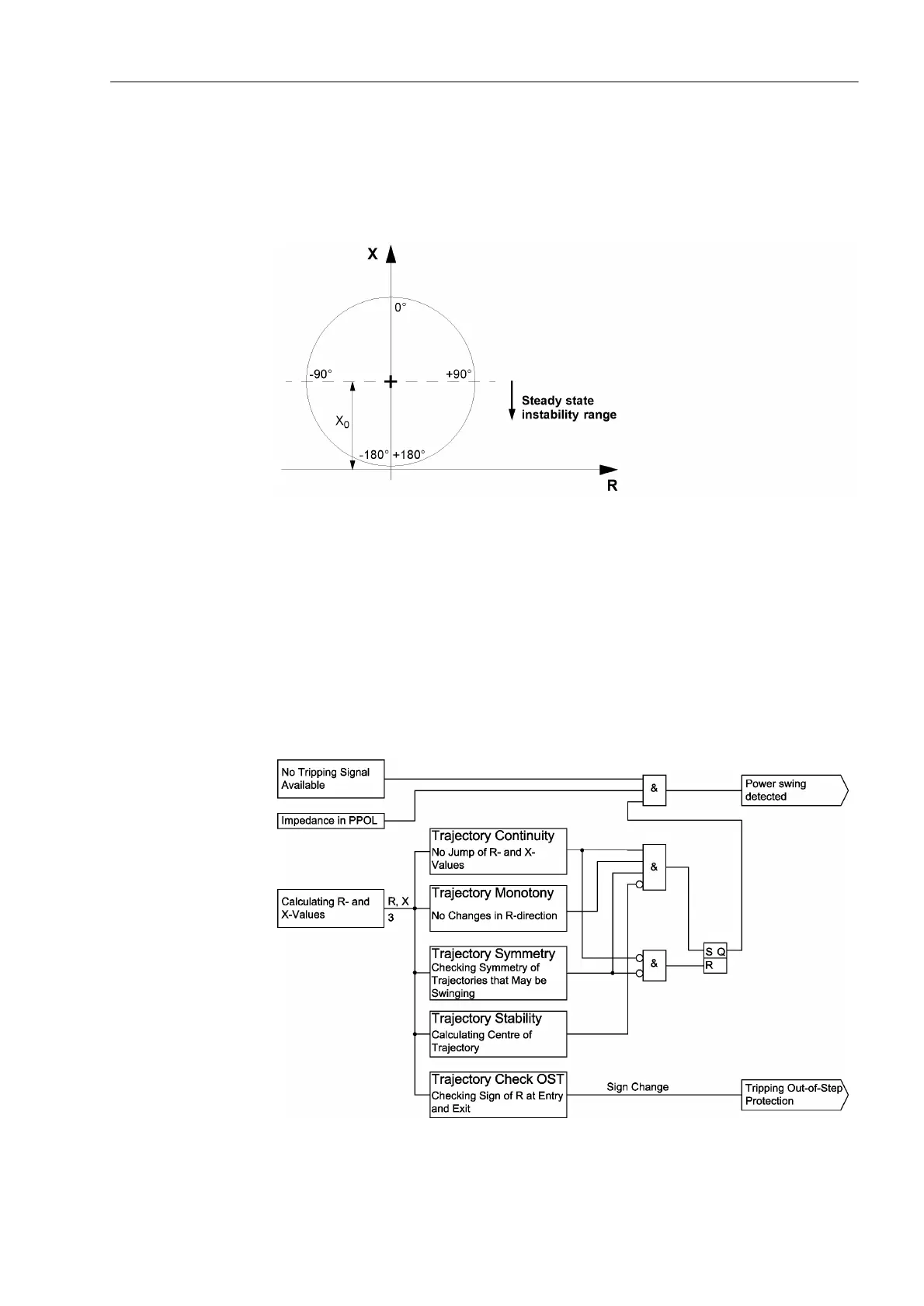
2-39 the range for steady state instability is shown. This range is detected in the dis-
tance protection relay. This is done by calculating the center of the ellipse and check-
ing if the actual measured X value is less than this value.
Figure 2-39 Steady state instability range
Trajectory
Symmetry
In addition to these measures, a comparison of the three phases is done to ensure that
they are symmetrical. During a power swing condition in the single pole open condi-
tion, only two of the three phases will have an impedance trajectory. In this case only
these 2 remaining phase trajectories are checked to ensure that they are symmetrical.
Power Swing
Detection
To ensure stable and secure operation of the power swing detection without risking un-
wanted power swing blocking during power system faults, a logical combination of a
number of measuring criteria are used.
Figure 2-40 Logic diagram of power swing detection

 Loading...


