2 Functions
272
7SA522 Manual
C53000-G1176-C155-3
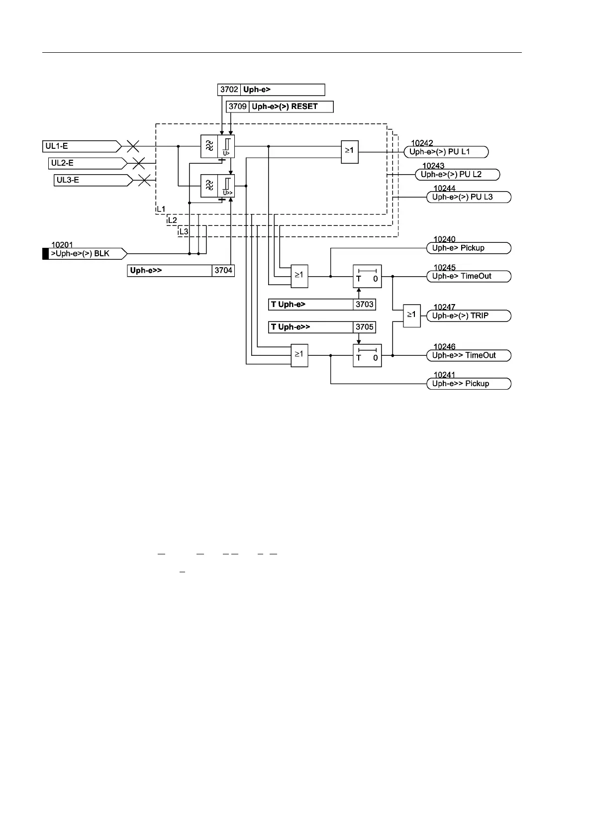
Figure 2-111 Logic diagram of the overvoltage protection for phase voltage
Overvoltage
Phase–Phase
The phase–phase overvoltage protection operates just like the phase–earth protection
except that it detects phase–to–phase voltages. Accordingly, phase–to–phase voltag-
es which have exceeded one of the stage thresholds 8SKSK! or 8SKSK!!are also
indicated. Beyond this, Figure 2-111 applies in principle.
The phase–phase overvoltage protection can also be blocked via a binary input
´!8SKSK!!%/.µ.
Overvoltage Posi-
tive Sequence
System U
1
The device calculates the positive sequence system according to its defining equation
U
1
=
1
/
3
·(U
L1
+ a·U
L2
+ a
2
·U
L3
)
where a
= e
j120°
.
The resulting single–phase AC voltage is fed to the two threshold stages 8! and
8!! (see Figure 2-112). Combined with the associated time delays 78! and 7
8!! these stages form a two-stage overvoltage protection for the positive sequence
system. Here too, the drop-out to pick-up ratio can be set.
The overvoltage protection for the positive sequence system can also be blocked via
a binary input ´!8!!%/.µ.

 Loading...


