2.15 Undervoltage and overvoltage protection (optional)
273
7SA522 Manual
C53000-G1176-C155-3
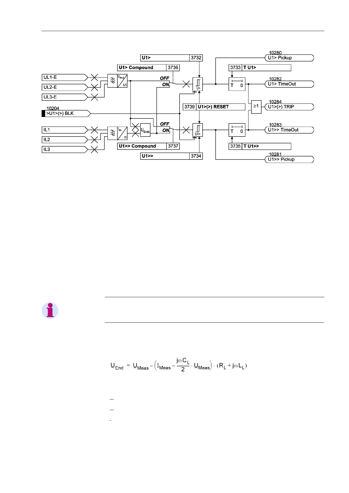
Figure 2-112 Logic diagram of the overvoltage protection for the positive sequence voltage system
Overvoltage U
1
with
Configurable Com-
pounding
The overvoltage protection for the positive sequence system may optionally operate
with compounding. The compounding calculates the positive sequence system of the
voltages at the remote line end. This option is thus particularly well suited for detecting
a steady-state voltage increase caused by long transmission lines operating at weak
load or no load due to the capacitance per unit length (Ferranti effect). In this case the
overvoltage condition exists at the other line end but it can only be removed by switch-
ing off the local line end.
For calculating the voltage at the opposite line end the device requires the line data
(inductance per unit length, capacitance per unit length, line angle, line length) which
were entered in the Power System Data 2 (Section 2.1.5.1) during configuration.
Compounding is only available if address is set to (QDEOZFRPS. In this
case the calculated voltage at the other line end is also indicated in the operational
measured values.
Note
Compounding is not suited for lines with series capacitors.
The voltage at the remote line end is calculated from the voltage measured at the local
line end and the flowing current by means of a PI equivalent circuit diagram (refer also
to Figure 2-113).
with
U
End
the calculated voltage at the remote line end,
U
Meas
the measured voltage at the local line end,
I
Meas
the measured current at the local line end,
C
L
the line capacitance,

 Loading...


