2.15 Undervoltage and overvoltage protection (optional)
279
7SA522 Manual
C53000-G1176-C155-3
Undervoltage Posi-
tive Sequence
System U
1
The device calculates the positive sequence system according to its defining equation
U
1
=
1
/
3
·(U
L1
+ a·U
L2
+ a
2
·U
L3
)
where a
= e
j120°
.
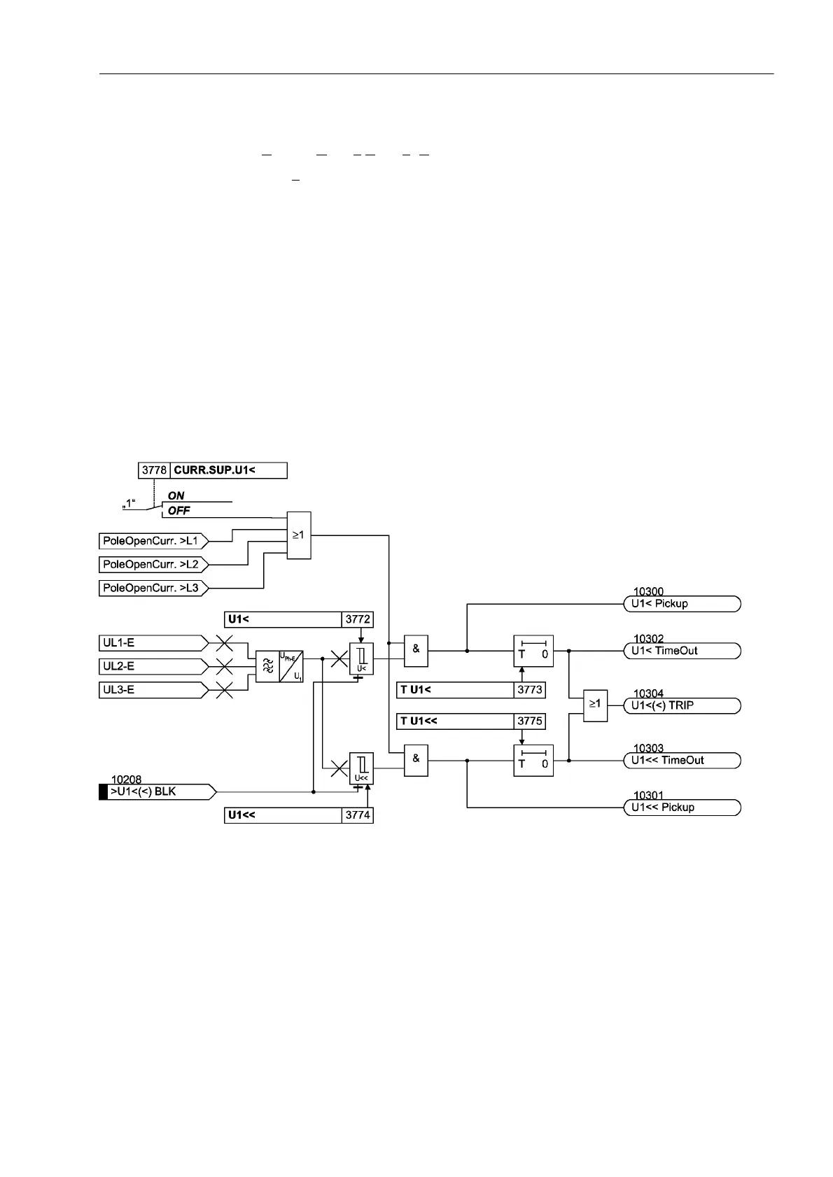
The resulting single–phase AC voltage is fed to the two threshold stages 8 and
8 (see Figure 2-117). Combined with the associated time delays 78 and 7
8 these stages form a two-stage undervoltage protection for the positive sequence
system.
Current can be used as an additional criterion for the undervoltage protection of the
positive sequence system (current supervision &8556838). An undervoltage is
only detected if the current flow is detected in at least one phase together with the un-
dervoltage criterion.
The undervoltage protection for the positive sequence system can be blocked via the
binary input ´!8%/.µ. The stages of the undervoltage protection are automat-
ically blocked if voltage failure is detected (“Fuse–Failure–Monitor”, also see Section
2.19.1) or, if the trip of the mcb for the voltage transformer is indicated via the binary
input ´!)$,/)HHGHU97µ (internal blocking).
Figure 2-117 Logic diagram of the undervoltage protection for positive sequence voltage system
During single-pole dead time for automatic reclosure (using the internal automatic re-
closure function) the stages of the undervoltage protection are automatically blocked
in the positive sequence system so that they do not respond to the reduced voltage
caused by the disconnected phase in case the voltage transformers are located on the
outgoing side.

 Loading...


