2 Functions
82
7SA522 Manual
C53000-G1176-C155-3
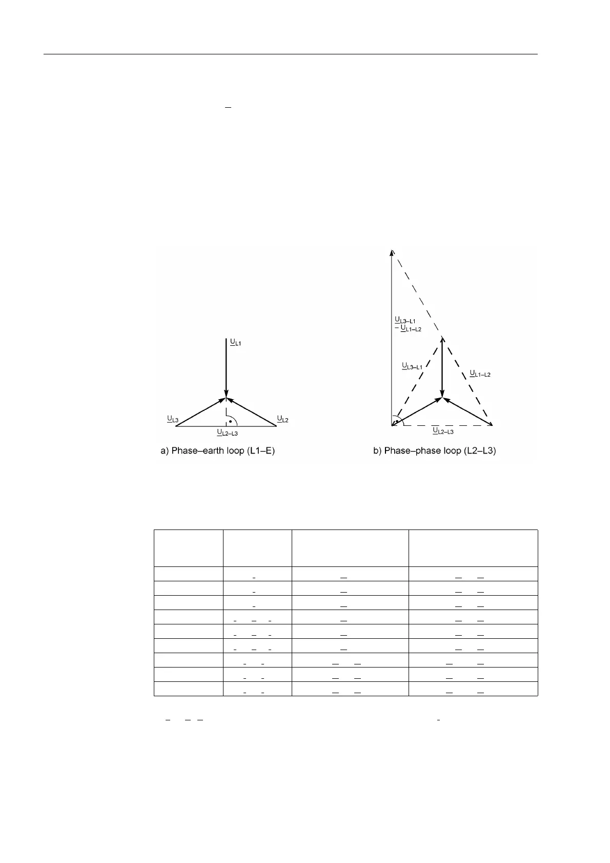
Determination of
Direction
For each loop an impedance vector is also used to determine the direction of the short-
circuit. Usually, Z
L
is used as for distance calculation. However, depending on the
“quality” of the measured values, different computation techniques are used. Immedi-
ately after fault inception, the short circuit voltage is disturbed by transients. The
voltage memorised prior to fault inception is therefore used in this situation. If the
steady-state short-circuit voltage (during a close-in fault) is even too small for direction
determination, an unfaulted voltage is used. This voltage is in theory quadrilateral to
the actual short-circuit voltage for both phase–earth loops as well as for phase–phase
loops (refer to Figure 2-19). This is taken into account when computing the direction
vector by means of a 90°–rotation. In Table 2-4 the allocation of the measured values
to the six fault loops for the determination of the fault direction is shown.
Figure 2-19 Direction determination with quadrature voltages
Table 2-4 Voltage and Current Values for the Determination of Fault Direction
1)
k
E
= Z
E
/Z
L
; if only one phase-earth loop picks up, the earth current I
E
is taken into account.
If there is neither a current measured voltage nor a memorized voltage available which
is sufficient for measuring the direction, the relay selects the )RUZDUG direction. In
Loop Measuring
Current (Direc-
tion)
Actual short-circuit
voltage
Quadrature voltage
L1-E I
L1
U
L1-E
U
L2
- U
L3
L2-E I
L2
U
L2-E
U
L3
- U
L1
L3-E I
L3
U
L3-E
U
L1
- U
L2
L1-E
1)
I
L1
- k
E
· I
E
1)
U
L1-E
U
L2
- U
L3
L2-E
1)
I
L2
- k
E
· I
E
1)
U
L2-E
U
L3
- U
L1
L3-E
1)
I
L3
- k
E
· I
E
1)
U
L3-E
U
L1
- U
L2
L1-L2 I
L1
- I
L2
U
L1
- U
L2
U
L2-L3
- U
L3-L1
L2-L3 I
L2
- I
L3
U
L2
- U
L3
U
L3-L1
- U
L1-L2
L3-L1 I
L3
- I
L1
U
L3
- U
L1
U
L1-L2
- U
L2-L3

 Loading...


