2.2 Distance protection
83
7SA522 Manual
C53000-G1176-C155-3
practice this can only occur when the circuit breaker closes onto a de-energized line,
and there is a fault on this line (e.g. closing onto an earthed line).
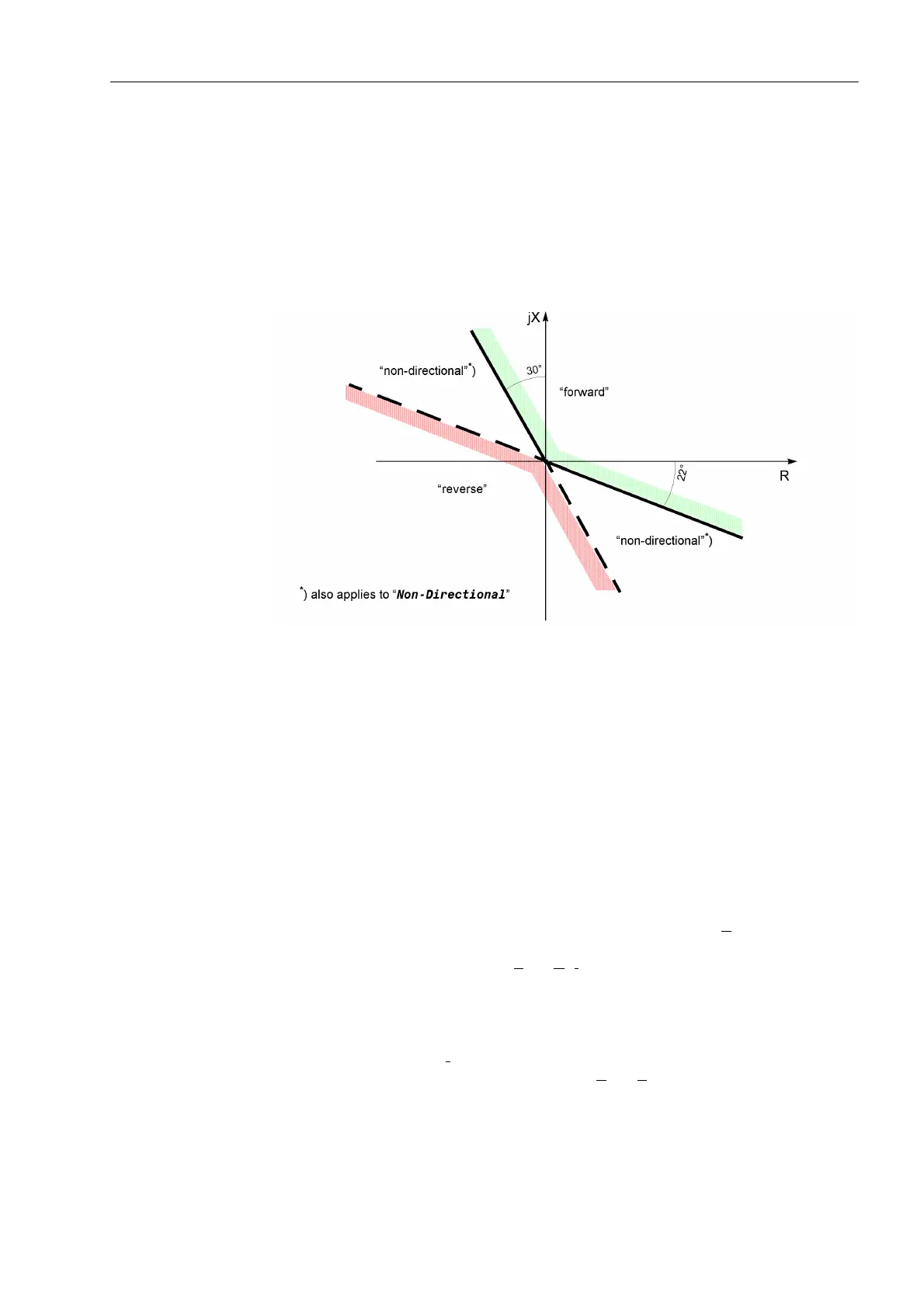
Figure 2-20 shows the theoretical steady-state characteristic. In practice, the position
of the directional characteristic when using memorized voltages is dependent on both
the source impedance as well as the load transferred across the line prior to fault in-
ception. Accordingly the directional characteristic includes a safety margin with
respect to the limits of the first quadrant in the R–X diagram (Figure 2-20).
Figure 2-20 Directional characteristic in the R-X-diagram
Since each zone can be set to )RUZDUG, 5HYHUVH or 1RQ'LUHFWLRQDO, different
(centrically mirrored) directional characteristics are available for )RUZDUG and
5HYHUVH. A non-directional zone has no directional characteristic. The entire tripping
region applies here.
Characteristics of
the Directional
Measurement
The theoretical steady-state directional characteristic shown in Figure 2-20 applies to
faulted loop voltages. In the case of quadrature voltages or memorized voltage, the
position of the directional characteristic is dependant on both the source impedance
as well as the load transferred across the line prior to fault inception.
Figure 2-21 shows the directional characteristic using quadrature or memorized
voltage as well as taking the source impedance into account (no load transfer). As
these voltages are equal to the corresponding generator voltage E
and they do not
change after fault inception, the directional characteristic is shifted in the impedance
diagram by the source impedance Z
S1
= E
1
/I
1
. For the fault location F
1
(Figure 2-21a)
the short-circuit location is in the forward direction and the source impedance is in the
reverse direction. For all fault locations, right up to the device location (current trans-
formers), a definite )RUZDUG decision is made (Figure 2-21b). If the current direction
is reversed, the position of the directional characteristic changes abruptly (Figure 2-
21c). A reversed current I
2
now flows via the measuring location (current transformer)
which is determined by the source impedance Z
S2
+ Z
L
. When load is transferred
across the line, the directional characteristic may additionally be rotated by the load
angle.

 Loading...


