2 Functions
96
7SA522 Manual
C53000-G1176-C155-3
Note
When switching onto a three-pole fault with the MHO circle, there will be no voltage in
the memory or unfaulted loop voltage available. To ensure fault clearance when
switching onto three-pole close-up faults, please make sure that in conjunction with
the configured MHO characteristic the instantaneous tripping function is always en-
abled.
Assignment to the
Circles and Zone
Pick-up
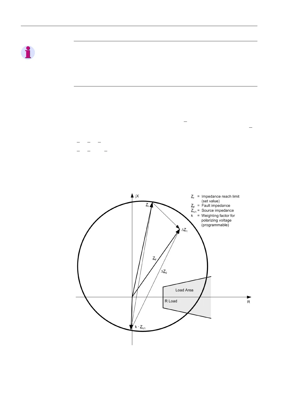
The assignment of measured values to the tripping zones of the MHO circles is done
for each zone by determining the angles between two difference phasors ∆Z
1
and ∆Z
2
(Figure 2-28). These phasors result from the difference between the two zeniths of the
circle diameter and the fault impedance. The zenith Z
r
corresponds to the set value for
the zone under consideration (Z
r
and ϕ
MHO
as shown in Figure 2-25), the zenith kZ
V
corresponds to the polarizing magnitude. Therefore the difference phasors are
∆Z
1
= Z
F
– Z
r
∆Z
2
= Z
F
– k · Z
S
In case of a fault exactly at the border of that MHO zone, ZF is located on the boundary
of the circle. In this case the angle between the two difference phasors is 90° (Thales–
theorem). Inside the circle the angle is greater than 90° and outside the circle it is
smaller than 90°.
Figure 2-28 Phasor diagram of the MHO circle measured values

 Loading...


