' $ ! $!& #$"&&"! (%& !' $$ !"
⋅
16
15
15
16
13
14
18
17
17
18
20
20
21
19
19
25
25
26
LED1
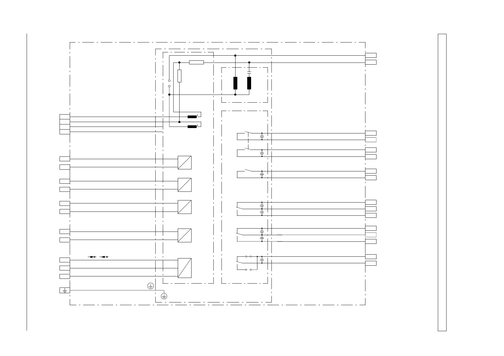
Flush mounting case / FLUSH MOUNTING CASE 7SD600*-*EA00-*DA0
Surface mounting case, lateral terminals, SURFACE MOUNTING CASE 7SD600*-*BA00-*DA0
14
13
21
26
30
31
=
30
31
L+
U
=
H
Stromversorgung / POWER SUPPLY
L-
KOMMANDORELAIS/COMMAND RELAYS
K1: AUS-Kommando/TRIP-COMMAND
K2: AUS-Kommando/TRIP-COMMAND
M3: Lockout aktiv/LOCKOUT ACTIVE
M1: Gerät bereit/DEVICE OPERATIVE
7
8
7
8
L+ Diff blo Kdo/DIFF BLO
E1:
9
10
9
10
L+ Lockout Quitt/LOCKOUT RESET
E2:
11
12
11
12
L+ LED-Quit/LED-RESET
E3:
29
28
29
28
A
B
27
27
GND
RS485
1
R
a
Hilfsadernanschluß/
PILOT WIRE TERMINALS
6
5
4
3
6
5
4
3
2
1
R
b
-T1
-T2
I
1
I '
1
ES
LED2
23
23
24
22
22
24
M2. Störung Ader/P-WIRE FAIL
LED1
MELDERELAIS/SIGNAL RELAY
Störschutzkondensatoren an den Relaisausgängen
Keramik, 4,7 nF, >250 V
Iinterference suppression capacitors at relay outputs,
ceramic, 4.7 nF, >250 V
(-K5)
(-K6)
(-K8)
(-K4)
(-K1)
(-K3)
EINGABE/INPUT
2
-BI1
-BI2
-BI3
~
Figure A1 Overview diagram of the differential protection 7SD600*-*B***- und 7SD600*-*E***-
 Loading...


