' $ ! $!& #$"&&"! Ċ (%& !' $$ !"
A - 32
Siemens AG ⋅ January 1999
Both conditions 1. and 2. (see section 5.2.5) must be
satisfied. Current transformer minimum data: 10P10.
A further condition 3 may be additionally used for diĆ
mensioning the current transformers if condition 2
cannot be satisfied because the current transformers
are too different.
The device can recognize an external short-circuit if
the current transformers at both ends of the line
transform the short circuit current without saturation
for a minimum period. The device then operates with
an increased stabilization and prevents overfunctioĆ
ning even when the differential current temporarily
exceeds the tripping value according to the stabilizaĆ
tion characteristic. The pick-up time of the saturation
detector depends on the value of the external fault
current. The following table shows the relationship
between the value of the fault current and the pick-
up time of the detector. Since the saturation detector
responds at approx. 2.5 times the rated current floĆ
wing through the line/cable, the accuracy limit factor
must be multiplied by the ratio of transformer rated
current to rated line current to obtain the pick-up time
in the table. Usually this factor = 1, so that direct use
of the accuracy limit factor k' can be made.
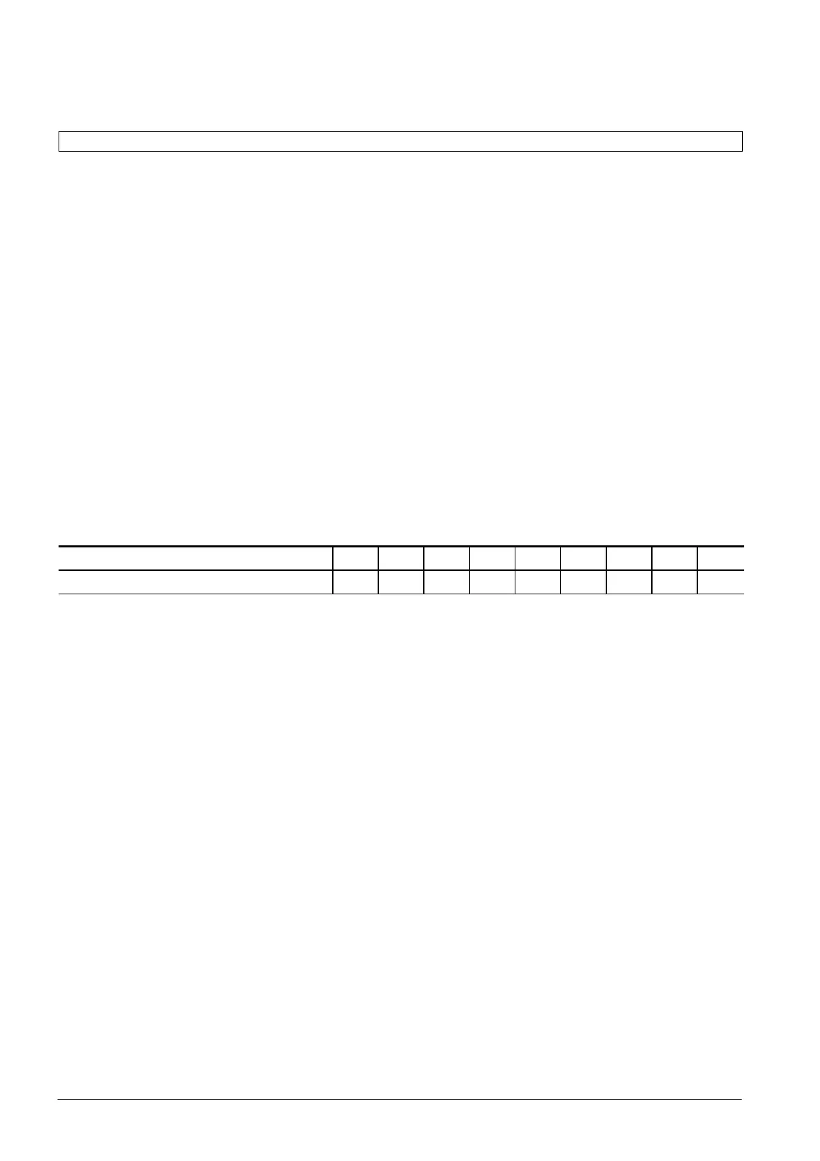
Table A.9.1 Pick-up time of the saturation detector depending on the maximum through fault current
relative to the rated line current
Fault current relative to the rated line current 3 2.5 4 5 7.5 10 10
Pick-up time of the saturation detector t
m
(ms) 12 10 9 7 5 5
The accuracy limit factor gives the ratio of maximum
fault current to rated current of the transformer. It is
calculated according to condition 1 from the maxiĆ
mum through fault current and the transformer rated
current. If this factor is multiplied by the overdimenĆ
sioning factor 4, the necessary accuracy limit factor
kn' is obtained at which the saturation-free transmisĆ
sion time of the current transformer is reached accorĆ
ding to table A.9.1. Factor 4 takes into account the
off-set of external short-circuits. This dimensioning
rule applies in approximation to systems with time
constants up to 100 ms and accuracy limit factors
greater than 2.5. Factor 4 therefore represents a simĆ
plification which covers most applications.
If exact calculation of the overdimensioning factor is
necessary because, for example, large system time
constants exist, factor 4 is not recommended. From
the saturation-free time t
m
the transformer time conĆ
stant t
w
and the circuit frequency w (2*PI*f) must be
calculated using the following equation:
Y=1+w*t
n
*t
w
/(t
n
-t
w
) * (exp(-t
m
/t
w
))
Example: transformer time constant t
w
= 5 s, saturaĆ
tion-free time t
m
= 0.01 s, f = 50 Hz ³ w = 314 1/s,
system time constant t
n
= 0.1 s. Y calculated with
formula equal 4.
3.1Necessary operational accuracy limit factor at line
end 1 for the saturation-free time according to the
table:
kn
1
' = 4*I
kd, max
/I
Npr
(exact: kn
1
' = Y*I
kd, max
/I
Npr
)
3.2Necessary operational accuracy limit factor at line
end 2 for the saturation-free time according to the
table:
kn
2
' = 4*I
kd, max
/I
Npr
(exact: kn
2
' = Y*I
kd, max
/I
Npr
)
The advantage is that conditions 3.1 and 3.2 are indeĆ
pendend of the respective CT burdens. On the other
hand, it leads to approx. 4 times higher requirements
of the operational accuracy limit factor than given by
the steady-state dimensioning rules according to 1
and 2.

 Loading...


