' $ ! $!& #$"&&"! Ċ (%& !' $$ !"
5 - 23
Siemens AG ⋅ January 1999
A
B
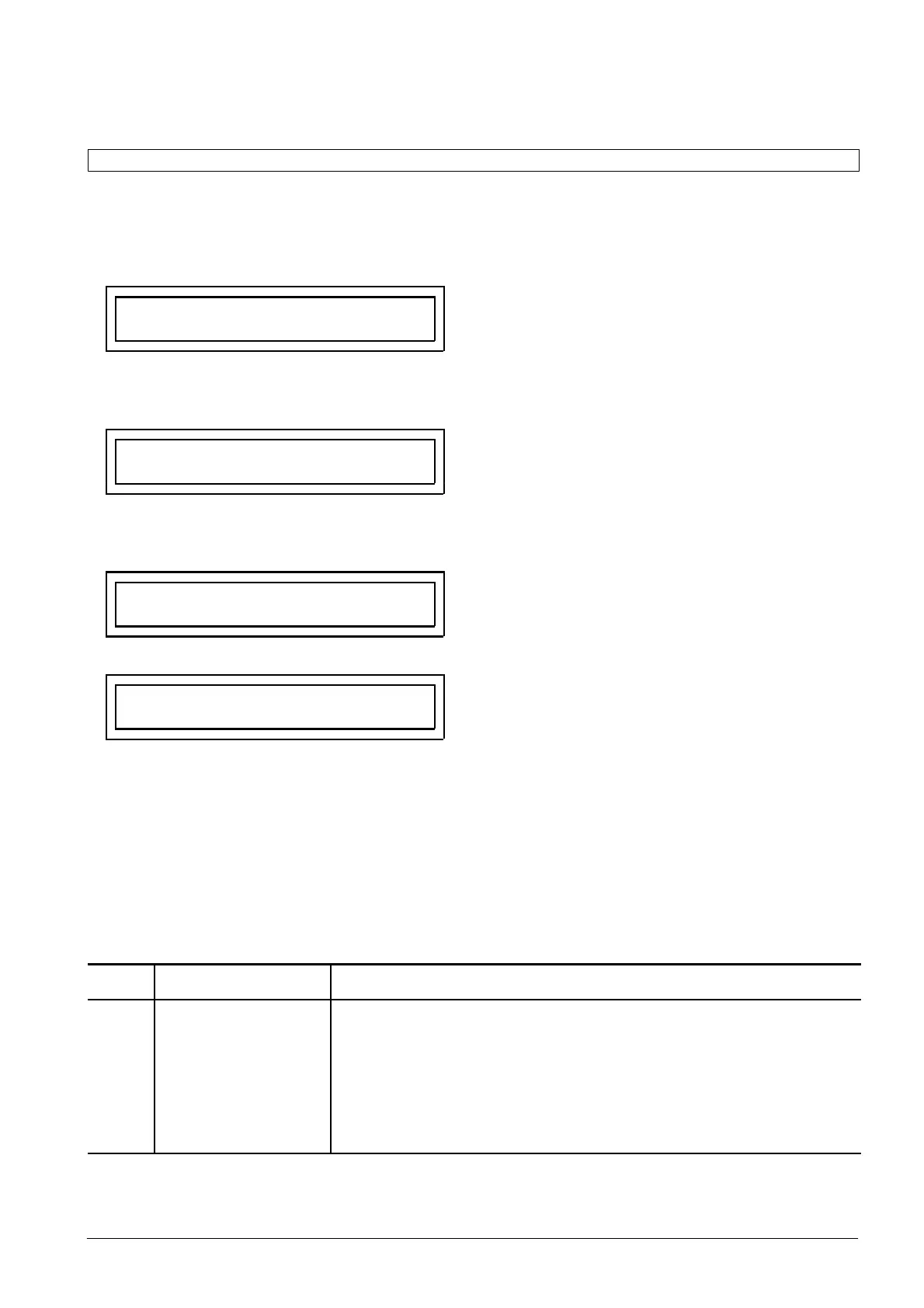
6 1 R O U T
B I
"
Beginning of the block "Marshalling of binary inputs"
Use the " key to go to the first binary input:
A
B
6 1 R O U T
B I 1
"
Assignment of binary inputs 1
Switch to the selection level with the "key:
A
6 1 B I 1 1
> Res. LED
B
Reset memorized LED, Fno. 5;
activated with voltage: if input is activated, the LEDs
are reset
A
6 1 B I 1 2
not a l l.
Y
B
No further functions are activated by input 1.
The "+" key lets you call up all marshallable input
functions on the display once you have entered the
code word. The "-" key also lets you scroll backĆ
wards through the list of alternatives. The required
function is confirmed with the enter key . Additional
functions under further index numbers (1 to 10) can
then be selected for binary input 1 using the B key.
Each selection must be confirmed with the E key. If
the slot of a physical module is not assigned, the
"not all." function (not allocated) is selected.
You can exit the selection level of binary input 1 with
the A key. The B key takes you to the next binary
input.
Table 5.1 Marshallable binary input functions
Fno. Short text
(display on LCD)
Logical function
2
5
1157
3003
3008
3303
3306
3333
3363
not all.
>Res. LED
>CBcl
>DIFblk
>Res.LO
>REM blk
>Rem.Tr.
>Rem.Tr.bl
>PWM bl
Input has not been allocated to a function
Reset LEDs
Circuit-breaker auxiliary contact: all poles activated
Blocking of DIF protective function
Reset Lockout function
Blocking of remote tripping
Inter trip of remote station
Blocking of trip by remote station
Blocking of pilot wire monitoring
 Loading...


