' $ ! $!& #$"&&"! Ċ (%& !' $$ !"
5 - 8
Siemens AG ⋅ January 1999
If the current transformers of the two line ends have
different primary nominal currents, the currents need
to be matched via the matching transformer. MatĆ
ching is carried out at the line end with the lower priĆ
mary nominal current.
As current inputs are galvanically isolated in the
4AM4930, the matching transformers can be inserted
in an auto-transformer mode. This makes better use
of the rating of the matching transformer and enables
implementation of a lower-rating type, such as the
4AM51 70-7AA. Figure 5.6 shows a sample connecĆ
tion.
The actual transformation ratio of the matching transĆ
former is determined as follows:
r
I
minimum + minimum
I
NĂprimary
Ă forĂ higherĂ ratedĂ current
I
NĂprimary
Ă forĂ lowerĂ ratedĂ current
This means that the turn ratio is
N
1
N
2
minimum + minimum
I
NĂprimary
Ă forĂ lowerĂ ratedĂ current
I
NĂprimary
Ă forĂ higherĂ ratedĂ current
with
N
1
- relative number of turns of the side facing the
main current transformer,
N
2
- relative number of turns of the side facing the
summation transformer.
Example:
Current transformer at line end : 500 A/1 A
Current transformer at line end : 400 A/1 A
Matching is carried out at line end :
N
1
N
2
+
I
NĂprimary
Ă forĂ lowerĂ ratedĂ current
I
NĂprimary
Ă forĂ higherĂ ratedĂ current
N
1
N
2
+
400Ă A
500Ă A
+ 0, 8Ă correspondsĂ toĂ e.g.Ă 40ń50Ă turns
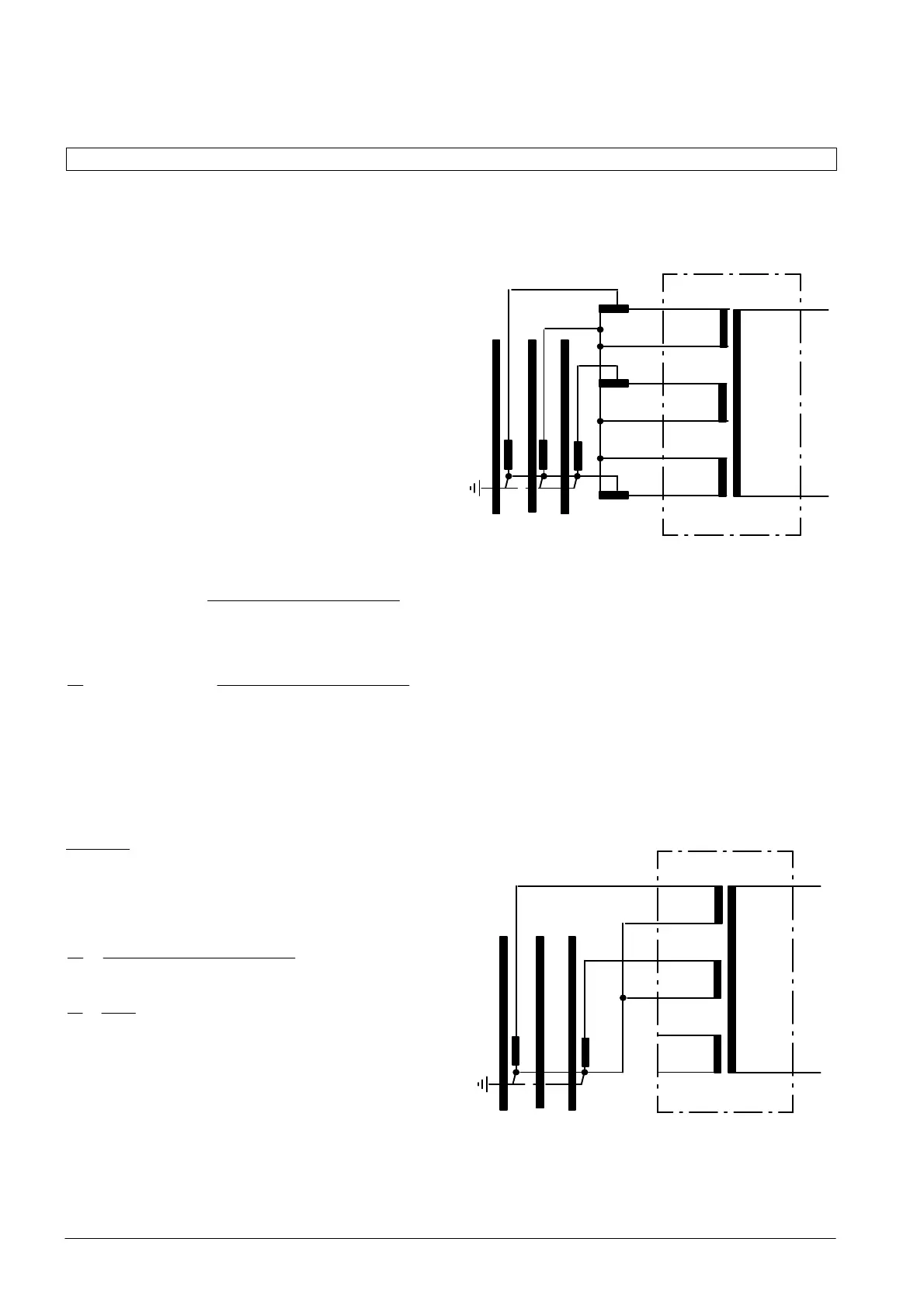
If the earth-fault sensitivity is to be increased in acĆ
cordance with section 5.2.4.3, the matching transforĆ
mer inserted in the earth current path, as shown in
Figure 5.6, can also be used for this purpose.
L1 L2 L3
MT
N
1
N
1
N
1
N
2
N
2
N
2
MT
1
3
2
Pluggable links D-G
B-E
C
H
A
F
L
M
Y
Z
Figure 5.6 Matching unequal primary currents
If a system without an earthed neutral only has two
current transformers, the phase on the device wiĆ
thout a current transformer remains free (Figure 5.7).
In the case of a double earth fault, the fault is not deĆ
tected by the protection. This must conform to the
double earth fault preference in the whole of the elecĆ
trically connected system. Please note that the same
phase must also be free at the other line end, even if
it is fitted with three current transformers.
MT
L1 L2 L3
Pluggable links D-G
B-E
C
A
F
L
M
Y
Z
H
1
3
2
Figure 5.7 Two-phase connection L1ā-āL3

 Loading...


