' $ ! $!& #$"&&"! Ċ (%& !' $$ !"
4 - 7
Siemens AG ⋅ January 1999
The differential and stabilizing current are determined
from the sampled values of the currents. The diffeĆ
rential current is filtered to pass the fundamental
wave in order to suppress DC components and higher
harmonics. The fundamental frequency component of
the differential current and the r.m.s. value of the staĆ
bilizing current are calculated for the evaluation.
To explain the method of operation, three important
states with ideal measured values are looked at:
1. Through-current with healthy line or external fault:
2
flows out of the line, i.e.
2
=-
1
;
and |
2
|=|
1
|
diff
=|
1
+
2
|=|
1
-
1
|=0
stab
=|
1
|+|
2
|=|
1
|+|
1
|=2|
1
|
No tripping quantity (I
diff
= 0); the stabilization
(I
stab
) corresponds to double the through-current.
2. Internal short-circuit, infeed from both sides with
e.g. equal currents:
2
=
1
then applies; as well as |
2
|=|
1
|
diff
=|
1
+
2
|=|
1
+
1
|=2|
1
|
stab
=|
1
|+|
2
|=|
1
|+|
1
|=2|
1
|
Tripping quantity (I
diff
) and stabilizing quantity (I
stab
)
are of equal magnitude and correspond to the
overall through fault current.
3. Internal short-circuit, infeed from one side only:
The following then applies
2
=0
diff
=|
1
+
2
|=|
1
+0|=|
1
|
stab
=|
1
|+|
2
|=|
1
|+0=|
1
|
Tripping quantity (I
diff
) and stabilizing quantity (I
stab
)
are of equal magnitude and correspond to the sinĆ
gle-end through fault current.
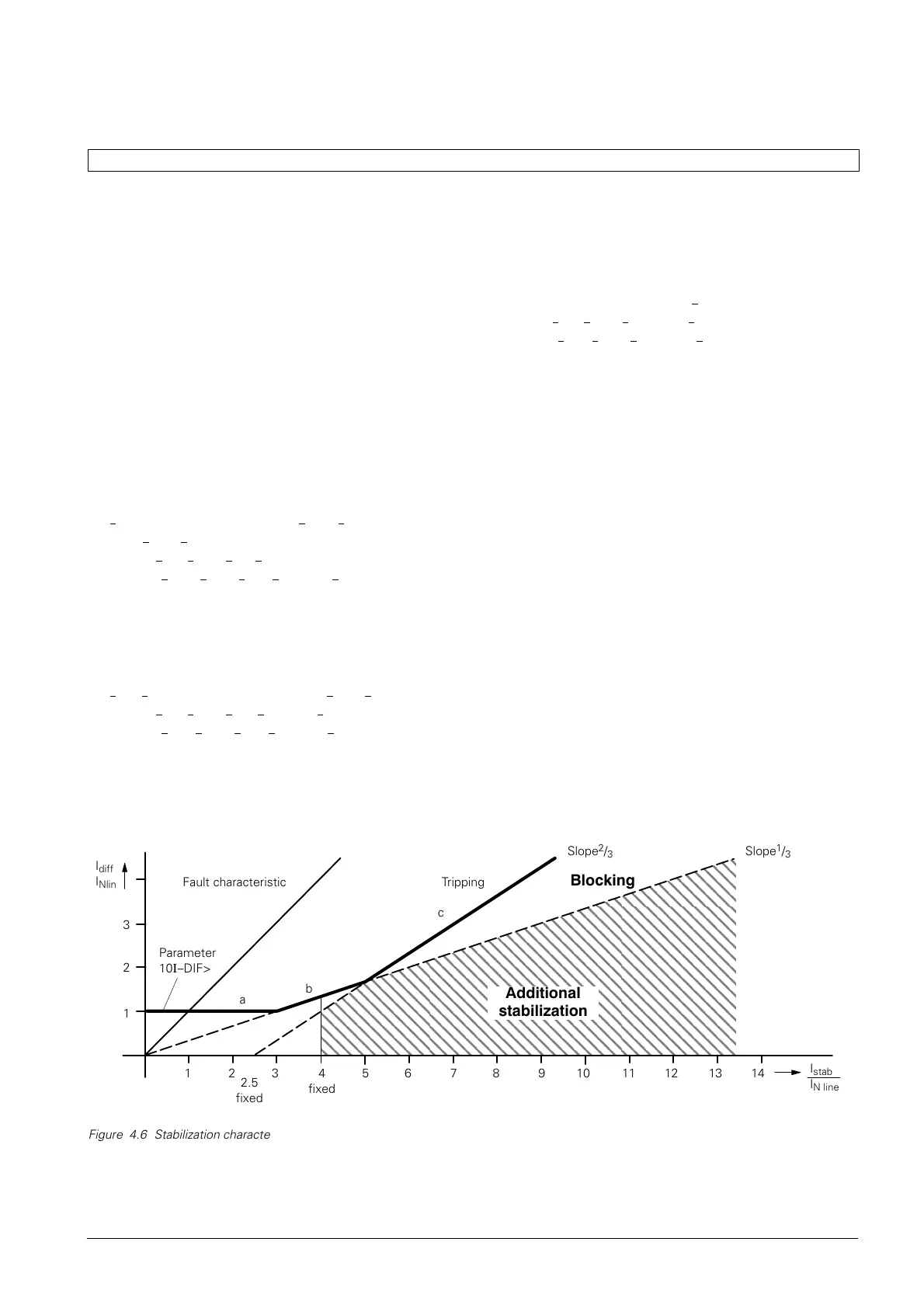
Thus, in the case of an internal fault; I
diff
=I
stab
. The
locus curve for internal faults in the tripping diagram
(see Figure 4.6) is represented by a straight line with
a45_ inclination. Figure 4.6 shows the overall stabiliĆ
zation characteristic of the 7SD600. The "a" segment
of the characteristic represents the sensitivity thresĆ
hold of the differential protection. Segment "b" consiĆ
ders current proportional measuring errors resulting
from transformation errors in the current transforĆ
mers, summation CTs and input CTs of the device. In
the high-current range, where current transformer
saturation may occur, segment "c" provides more
stabilization. A further, special method of handling
current transformer saturation (additional stabilization)
is described in section 4.3.5.
The differential protection locates the determined curĆ
rents I
diff
and I
stab
in the stabilization characteristic as
shown in Figure 4.6. If these quantities correspond to
a point within the tripping zone, tripping occurs if the
local current exceeds a minimum value (local current
threshold, see section 4.3.7).
ÇÇÇÇÇÇÇÇÇÇÇÇÇÇÇÇÇÇ
ÇÇÇÇÇÇÇÇÇÇÇÇÇÇÇÇÇÇ
ÇÇÇÇÇÇÇÇÇÇÇÇÇÇÇÇÇÇ
ÇÇÇÇÇÇÇÇÇÇÇÇÇÇÇÇÇÇ
ÇÇÇÇÇÇÇÇÇÇÇÇÇÇÇÇÇÇ
ÇÇÇÇÇÇÇÇÇÇÇÇÇÇÇÇÇÇ
ÇÇÇÇÇÇÇÇÇÇÇÇÇÇÇÇÇÇ
ÇÇÇÇÇÇÇÇÇÇÇÇÇÇÇÇÇÇ
ÇÇÇÇÇÇÇÇÇÇÇÇÇÇÇÇÇÇ
ÇÇÇÇÇÇÇÇÇÇÇÇÇÇÇÇÇÇ
I
stab
I
N line
Fault characteristic Tripping
Blocking
Additional
stabilization
I
diff
I
Nlin
1
2
3
1523 4
fixed
6 7 8 9 10 11 12 13 14
c
b
a
2.5
fixed
Slope
1
/
3
Slope
2
/
3
Parameter
10-DIF>

 Loading...


