Functions
2.10 Monitoring Functions
SIPROTEC, 7SK80, Manual
E50417-G1140-C344-A4, Release date 08.2010
157
Measurement Value Acquisition – Currents
The monitoring of the device-internal measured-value acquisition of the currents can be effected via the current
sum monitoring.
Up to four input currents are measured by the device. If the three phase currents and the ground current from
the current transformer neutral point are connected with the device, the sum of the four digitized currents must
be zero. This also applies in the event of a possible transformer saturation. For that reason – in order to elimi-
nate pickup upon transformer saturation – this function is only available in a Holmgreen-connection (see also
Section 2.1.3.2). Faults in the current circuits are recognized if
I
F
= | i
A
+ i
B
+ i
C
+ i
E
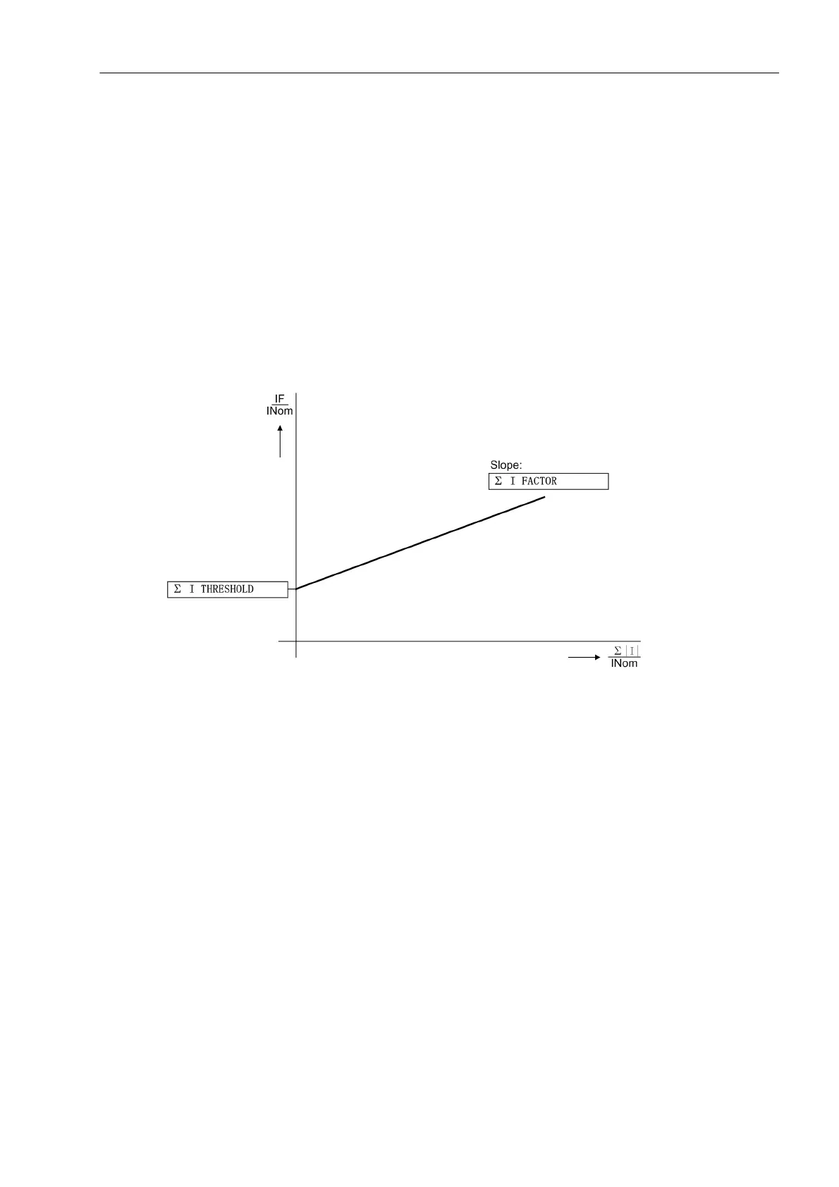
| > Σ I THRESHOLD + Σ I FACTOR Σ | I |
Σ I THRESHOLD (adress 8106) and Σ I FACTOR (adress 8107) are programmable settings. The component
Σ I FACTOR · Imax takes into account the permissible current proportional ratio errors of the input transformer
which are particularly prevalent during large short-circuit currents (Figure ). The dropout ratio is about 97 %.
Figure 2-45 Current Sum Monitoring
An error in the current sum results in the message „Failure Σ I“ (No. 162) and blocking of the protection
function. Furthermore, a fault log is initiated for a period of 100 ms.
The monitoring can be switched off.
The monitoring is available subject to the following conditions:
• The three phase currents are connected to the device (address 251 A, B, C, (Gnd))
• The ground current of the current transformer neutral point is connected to the fourth current input (I
4
)
(Holmgreen-connection). This is communicated to the device in the Power System Data 1 via address
280 YES.
• The fourth current input is normally designed for a I
4
–transformer. In case of a sensitive transformer type,
this monitoring is not available.
• The settings CT PRIMARY (address 204) and Ignd-CT PRIM (address 217) must be the same.
• The settings CT SECONDARY (address 205) and Ignd-CT SEC (address 218) must be the same.
The following logic diagram illustrates the operational mode of the current sum monitoring.

 Loading...


