Functions
2.10 Monitoring Functions
SIPROTEC, 7SK80, Manual
E50417-G1140-C344-A4, Release date 08.2010
160
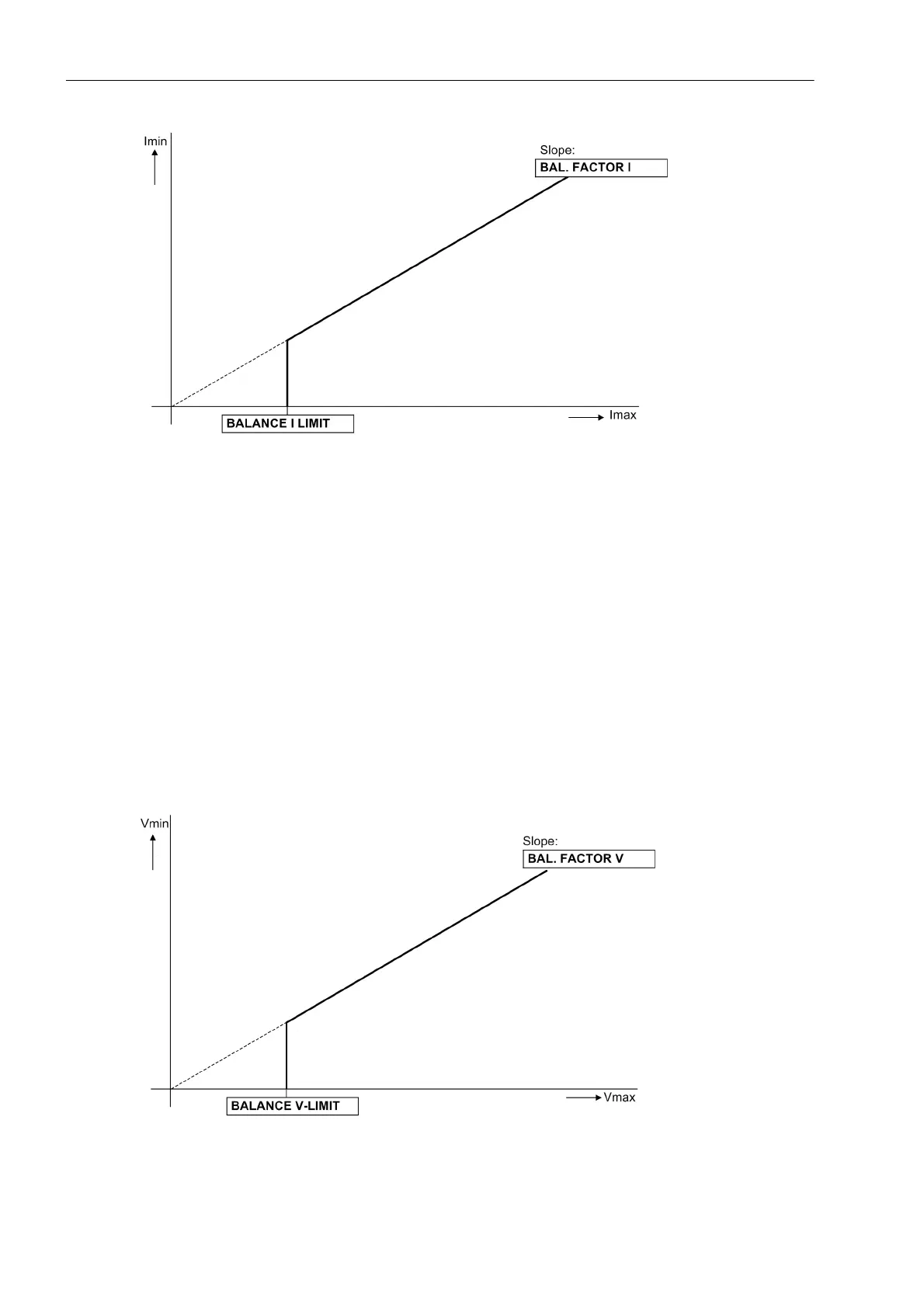
Figure 2-47 Current symmetry monitoring
Voltage Symmetry
During normal system operation, a certain symmetry among the voltages is to be assumed. Since the phase-
to-phase voltages are insensitive to ground faults, the phase-to-phase voltages are used for the symmetry
monitoring. Depending of the connection mode, either the measured quantities or the calculated phase-
tophase voltages are used. From the phase-to-phase voltages, the rectified average values are generated and
checked for symmetry of their absolute values. The smallest phase voltage is compared with the largest phase
voltage. Asymmetry is recognized if
| V
min
| / | V
max
| < BAL. FACTOR V as long as | V
max
| > BALANCE V-LIMIT. Where V
max
is the highest of the
three voltages and V
min
the smallest. The symmetry factor BAL. FACTOR V (address 8103) represents the
allowable asymmetry of the conductor voltages while the limit value BALANCE V-LIMIT (address 8102) is the
lower limit of the operating range of this monitoring (see Figure 2-48). Both parameters can be set. The dropout
ratio is about 97%.
This failure is thus located below the curve for all values and is reported as „Fail V balance“.
Figure 2-48 Voltage symmetry monitoring

 Loading...


