Functions
2.11 Ground Fault Protection 64, 67N(s), 50N(s), 51N(s)
SIPROTEC, 7SK80, Manual
E50417-G1140-C344-A4, Release date 08.2010
178
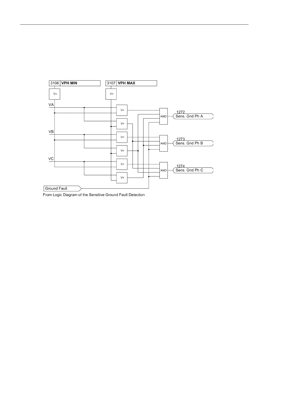
After the voltage element picks up due to detection of a displacement voltage, the grounded phase is identified,
if possible. For this purpose, the individual phase-to-Ground voltages are measured or calculated, irrespective
of the connection type of the voltage transformers. If the voltage magnitude for any given phase falls below the
set threshold VPH MIN, that phase is detected as the grounded phase as long as the remaining phase-to-
Ground voltages exceed the set threshold VPH MAX.
Figure 2-57 Determination of Grounded Phase
Current Elements
The current elements for ground faults operate with the magnitudes of the ground current. It is sensible to
employ them only where the magnitude of the ground current can be used to specify the ground fault. This may
be the case on grounded systems (solid or low-resistance) or on electrical machines which are directly con-
nected to the busbar of an isolated power system, when in case of a network ground fault the machine supplies
only a negligible ground fault current across the measurement location, which must be situated between the
machine terminals and the network, whereas in case of a machine ground fault the higher ground fault current
produced by the total network is available. Ground current protection is mostly used as backup protection for
high resistance ground faults in solid or low resistance grounded systems when the main fault protection does
not pickup.
For ground current detection,a two-element current/time Curve can be set. Analogeous to the time overcurrent
protection, the high-set current stage is designated as 50Ns-2 PICKUP and 50Ns-2 DELAY and is provided
with a definite time characteristic. The overcurrent element may be operated with either a definite time delay
(50Ns-1 PICKUP and 50Ns-1 DELAY) or with a user-defined Curve (51Ns PICKUP and 51NsTIME DIAL).
The characteristics of these current elements can be configured. Each of these elements may be directional or
non-directional.
In case of capacitive voltage measurement, the current elements operate non-directional only since an exact
angle measurement is not ensured when using the voltage V
0
.
The pickup of the definite time overcurrent protection can be stabilized by the configured dropout delay time
(address 3121 50Ns T DROP-OUT).

 Loading...


