Functions
2.11 Ground Fault Protection 64, 67N(s), 50N(s), 51N(s)
SIPROTEC, 7SK80, Manual
E50417-G1140-C344-A4, Release date 08.2010
180
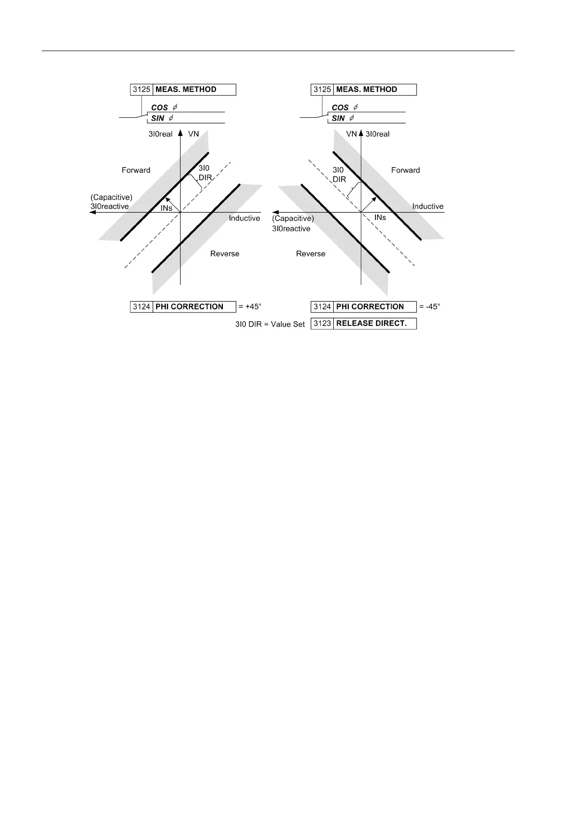
Figure 2-59 Directional characteristic for cos–ϕ–measurement
Fault direction is calculated with the zero sequence values from the ground current 3I
0
and displacement
voltage V
0
or 3 · V
0
. With these quantities ground active power and ground reactive power is calculated.
The calculation algorithm used filters the measured values so that it is highly accurate and insensitive to higher
harmonics (particularly the 3rd and 5th harmonics – which are often present in zero sequence currents). Direc-
tion determination relies on the sign of active and reactive power.
Since active and reactive components of the current - not the power - are relevant for pickup, current compo-
nents are calculated from the power components. When determining the ground fault direction the active or
reactive components of the ground current in reference to the displacement voltage as well as the direction of
the active and reactive power are evaluated.
For measurements of sin ϕ (for ungrounded systems) the following applies
• Ground fault (forward direction), if Q
0
< 0 and 3I0
reactive
> setting value (RELEASE DIRECT.),
• Ground fault (reverse direction), if Q
0
> 0 and 3I0
reactive
> setting value (RELEASE DIRECT.).
For measurements cos ϕ (for resonant grounded systems) the following applies
• Ground fault (forward direction), if P
0
> 0 and 3I0
active
> setting value (RELEASE DIRECT.),
• Ground fault (reverse direction), if P
0
< 0 and 3I0
active
> setting value (RELEASE DIRECT.).
If PHI CORRECTION is unequal 0°, the angle of the directional limit lines is calculated by adding up active and
reactive power components.

 Loading...


