Functions
2.11 Ground Fault Protection 64, 67N(s), 50N(s), 51N(s)
SIPROTEC, 7SK80, Manual
E50417-G1140-C344-A4, Release date 08.2010
185
Current Elements
There are two current elements available. Both elements operate directionally, whereby the tripping zones can
be set individually for each element (see margin heading „Tripping Area“).
In case of capacitive voltage measurement, the current elements operate non-directional only since an exact
angle measurement is not ensured when using the voltage V
0
.
Both elements are provided with a definite time characteristic. Two current/time elements are used for ground
fault protection. Analog to the time overcurrent protection function, the overcurrent element is named 50Ns-1
PICKUP and 50Ns-1 DELAY and the high-set element 50Ns-2 PICKUP and 50Ns-2 DELAY.
The pickup of the definite time overcurrent protection can be stabilized by the configured dropout delay time
(address 3121 50Ns T DROP-OUT).
Tripping Range
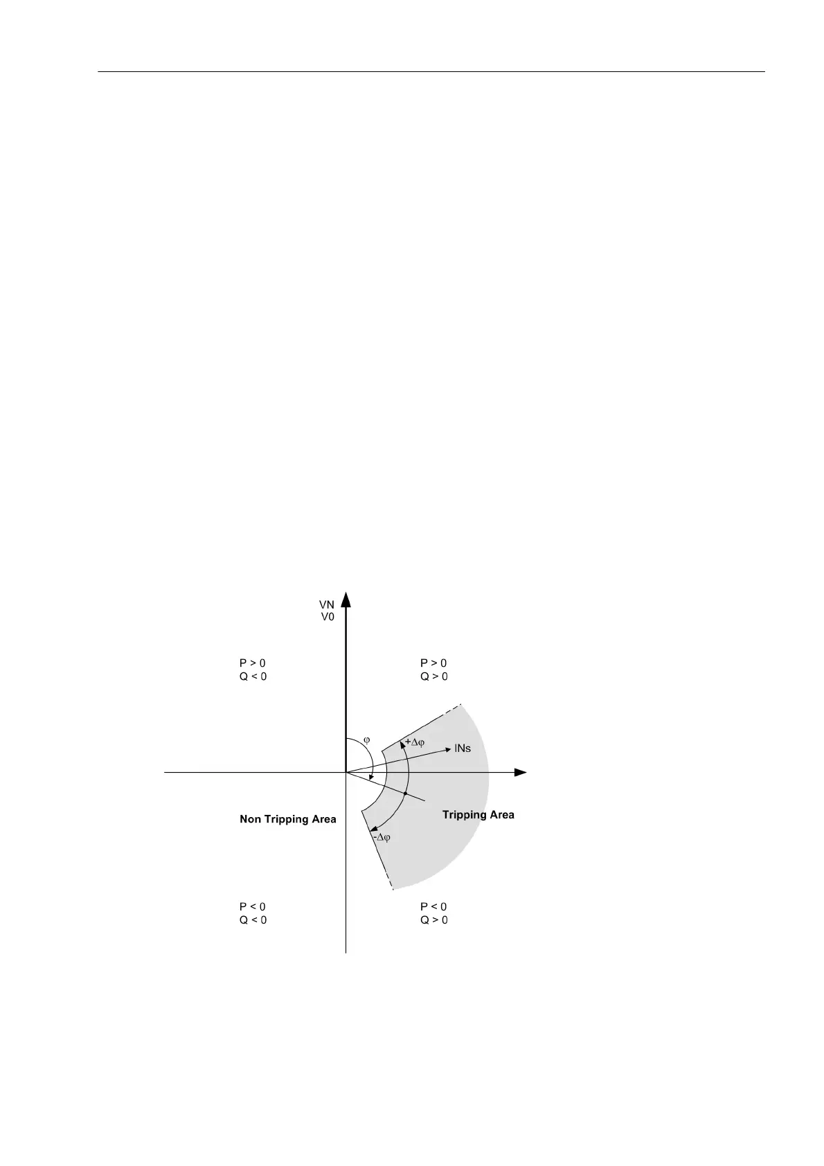
The U0/I0-ϕ characteristic is illustrated as a sector in the U0/I0 phasor diagram (see Figure 2-64). This sector
corresponds to the tripping area. If the cursor of the ground current is in this sector, the function picks up.
The tripping area is defined via several parameters: Via the angle ϕ (parameter 3154 50Ns-1 Phi or 3151
50Ns-2 Phi), the center of the zone with reference to the displacement voltage V
0
is set. Via the angle Δϕ
(parameter 3155 50Ns-1 DeltaPhi or 3152 50Ns-2 DeltaPhi), the zone is extended to both sides of the
center.
The zone is further limited downwards by minimum values of the displacement voltage and ground current.
These settable threshold values must be exceeded in order to be picked up.
Negative angle settings turn the tripping area in the „inductive“ direction, i.e. ground current inductive compared
to ground voltage.
Figure 2-64 Tripping range of V0/I0-ϕ characteristic

 Loading...


