Functions
2.15 Temperature Detection via RTD Boxes
SIPROTEC, 7SK80, Manual
E50417-G1140-C344-A4, Release date 08.2010
229
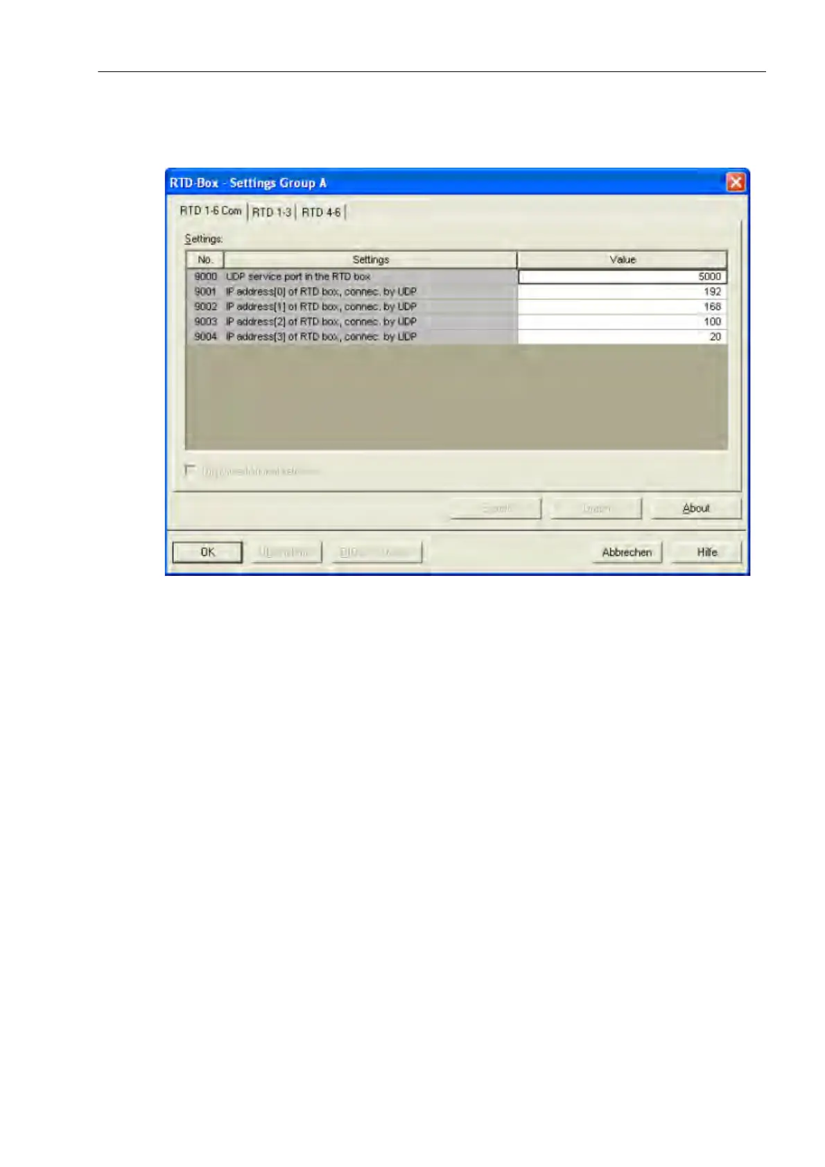
For RTD-Box 1 the IP adresse 192.168.100.20 is entered as follows:
Figure 2-89 DIGSI Setting of RTD-Boxes
Please consider that the IP adresses of the RTD-Boxes are in the same SubNetMask like the ethernet interface
(Port A).
Device Settings
The settings are the same for each input and are here shown at the example of measuring input 1.
Set the type of temperature detector for RTD 1 (temperature sensor for measuring point 1) at address 9011
RTD 1 TYPE. You can choose between Pt 100 Ω , Ni 120 Ω and Ni 100 Ω. If no temperature detector
is available for RTD 1, set RTD 1 TYPE = Not connected. This setting is only possible via DIGSI at „Display
Additional Settings“.
Address 9012 RTD 1 LOCATION informs the device on the mounting location of RTD 1. You can choose
between Oil, Ambient, Winding, Bearing and Other. The selection is not evaluated in the device but only
serves the purpose of providing information about the medium in which the temperature measurement is
carried out. This setting is only possible in DIGSI at „Display Additional Settings“.
You can also set an alarm temperature and a tripping temperature. Depending on the temperature unit selected
in the Power System Data (Section 2.1.1.2 in address 276 TEMP. UNIT), the alarm temperature can be ex-
pressed in degrees Celsius (°C) (address 9013 RTD 1 STAGE 1) or degrees Fahrenheit (°F) (address 9014
RTD 1 STAGE 1). The tripping temperature is set to degrees Celsius (°C) in address 9015 RTD 1 STAGE 2
or to degrees Fahrenheit (°F) at address 9016 RTD 1 STAGE 2.

 Loading...


