2 Functions
126
7UT613/63x Manual
C53000-G1176-C160-2
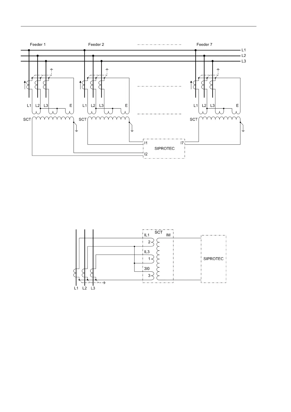
Figure 2-43 Busbar protection with connection via summation current transformers (SCT)
Different schemes are possible for the connection of the current transformers. The
same CT connection method must be used for all feeders of a busbar.
The scheme as illustrated in figure 2-44 is the most commonly used. The three input
windings of the summation transformer are connected to the CT currents I
L1
, I
L3
and
I
E
. This connection is suitable for all kinds of systems regardless of the conditioning of
the system neutral. It is characterised by an increased sensitivity for earth faults.
Figure 2-44 Summation Transformer Connection L1-L3-E
For a symmetrical three-phase current (where the earth residual component I
E
= 0)
the single-phase summation current is W = √3 times the winding unit value, as shown
in figure 2-45, i.e. the summation flux (ampere turns) is the same as it would be for
single-phase current √3 times the value flowing through the winding with the least
number of turns (ratio 1). For three-phase symmetrical fault currents equal to rated
current 1 x I
N
, the secondary single-phase current is I
M
= 100 mA. All relay character-
istic operating values are based on this type of fault and this current.
 Loading...


