2 Functions
202
7UT613/63x Manual
C53000-G1176-C160-2
The internal burden is often stated in the test report of the current transformer. If not
known, it can be derived from a DC measurement on the secondary winding.
Calculation Example:
Current transformer 800/5; 5P10; 30 VA with R
i
= 0.3 Ω
or
Current transformer 800/1; 5P10; 30 VA with R
i
= 5 Ω
Apart from the CT data, the resistance of the longest connection lead between the CTs
and the 7UT613/63x device must be known.
Restraint Consider-
ations for High-Im-
pedance Protection
The stability condition is based on the following simplified assumption: If there is an
external fault, one of the current transformers gets totally saturated. The other ones
will continue transmitting their (partial) currents. In theory, this is the most unfavour-
able case. Since, in practice, it is also the saturated transformer which supplies cur-
rent, a safety margin is automatically guaranteed.
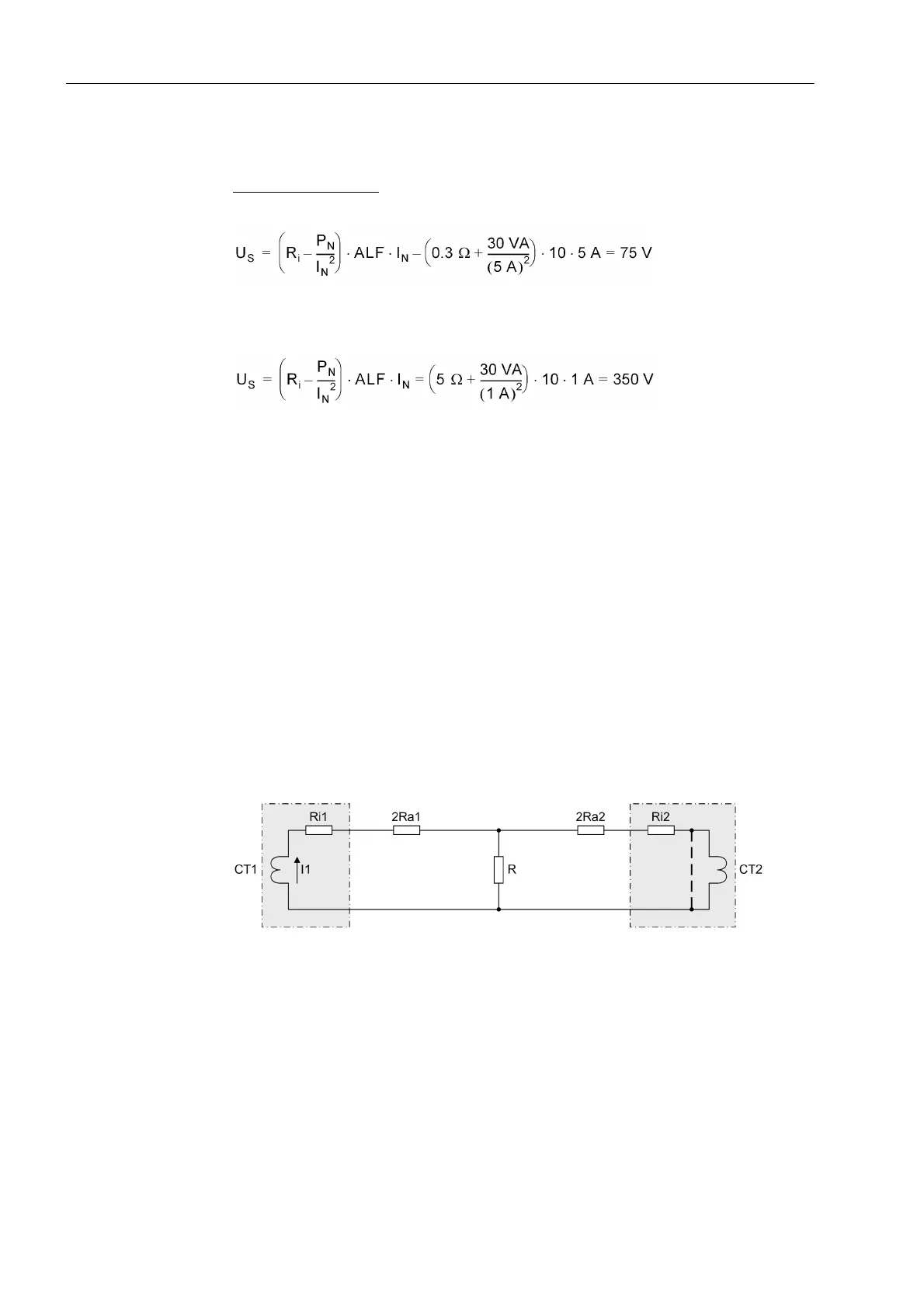
Figure 2-90 illustrates a simplified equivalent circuit. CT1 and CT2 are assumed as
ideal transformers with their inner resistance R
i1
and R
i2
. R
a
is the resistance of the
connecting cables between current transformers and resistor R. They are multiplied
by 2 as they have a go and a return line. R
a2
is the resistance of the longest connecting
cable.
CT1 transmits current I
1
. CT2 is saturated; this is shown by the dashed short-circuit
line. Due to saturation the transformer represents a low-resistance shunt.
A further requirement is R >> (2R
a2
+ R
i2
).
Figure 2-90 Simplified equivalent circuit of a circulating current system for high-impedance
protection
 Loading...


