2.8 Unbalanced Load Protection
217
7UT613/63x Manual
C53000-G1176-C160-2
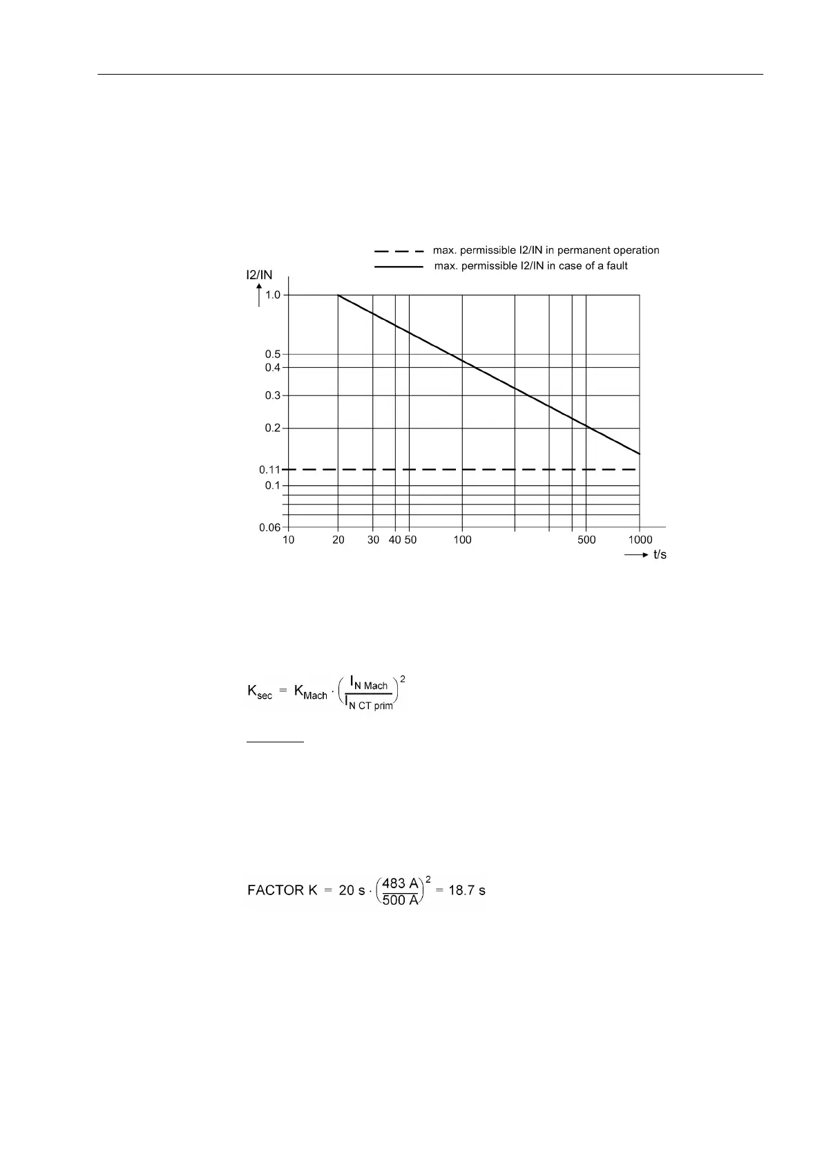
In example, figure 2-97, the permanently permissible asymmetrical load amounts to
11 % of the machine internal current and the K-factor K = 20. As the relevant measur-
ing location for asymmetrical load is usually assigned to the side of the machine to be
protected, the setting can be effected directly under address 4034 FACTOR K:
FACTOR K = 20.
Figure 2-97 Example of a pre-defined asymmetrical load diagram
If, however, the asymmetrical load protection must be set in amps secondary during
operation, also the K-factor must be converted as it refers to the machine internal cur-
rent. The following applies:
Example:
Machine I
N
= 483 A
I
2perm
= 11 % (salient-pole machine)
K-factor = 20 s
Current transformer 500 A/5 A
results in the setting value under address 4034 FACTOR K:
The setting value 4035 T COOL DOWN is defined as the time required by the protected
object to cool down from 100 % to 0 % during prior stress with permissible asymmet-
rical load I2>. If the machine manufacturer does not provide this information, the
setting value can be calculated by assuming an equal value for cool-down time and

 Loading...


