2 Functions
56
7UT613/63x Manual
C53000-G1176-C160-2
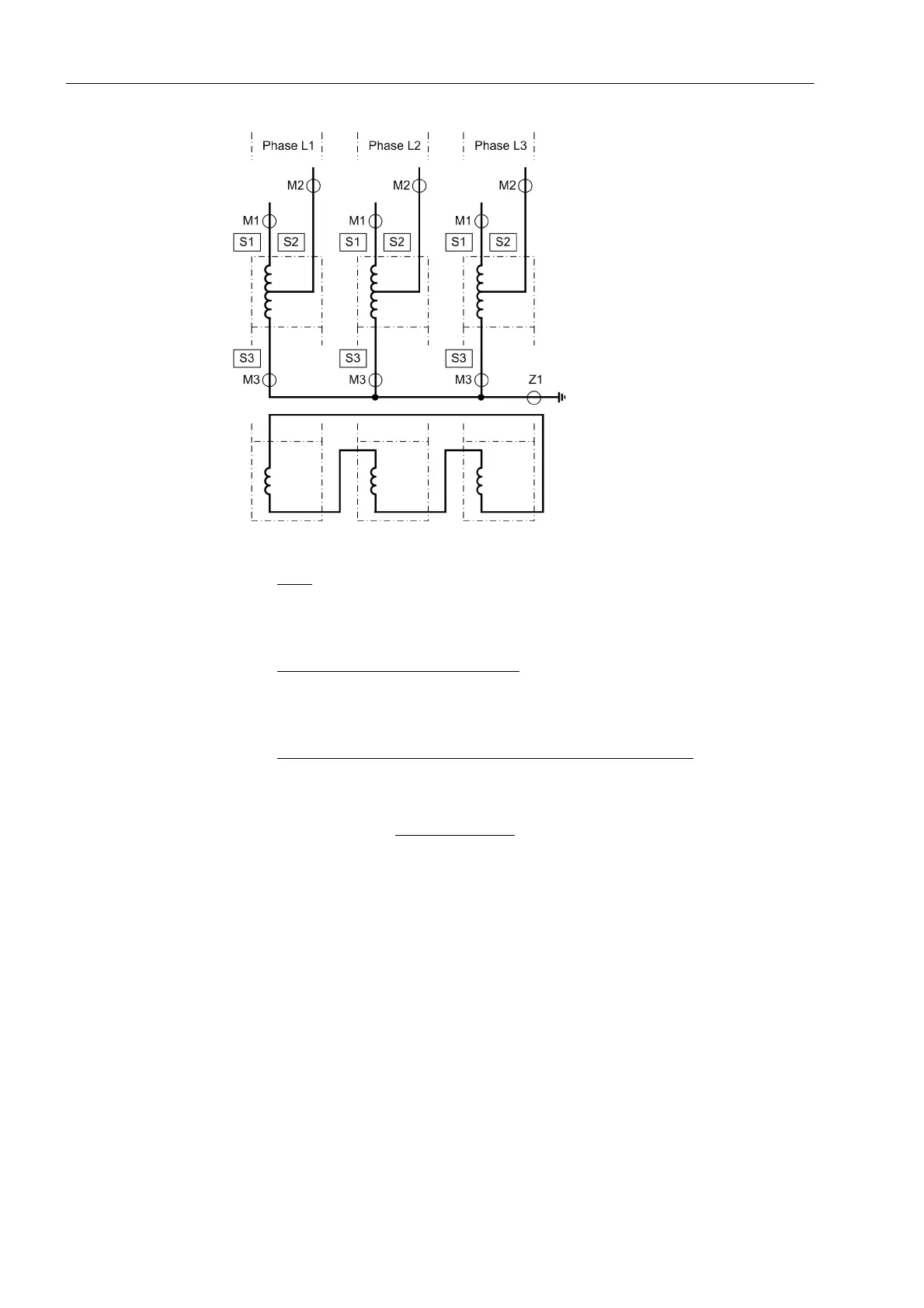
Figure 2-7 Topology of a transformer bank consisting of 3 single-phase auto-transformers,
topology definitions for a current comparison protection for each phase
Sides:
S1 High voltage side of the auto-connected winding of the main protected object
S2 Low voltage side (tap) of the auto-connected winding of the main protected object
S3 Starpoint side of the auto-connected winding of the main protected object
Measuring locations 3-phase, assigned
:
M1 Measuring location, assigned to the main protected object, side 1
M2 Measuring location, assigned to the main protected object, side 2
M3 Measuring location, assigned to the main protected object, side 3
Auxiliary measuring locations, 1-phase, assigned to the main object
:
X1 Measuring location, assigned to the main protected object, side 1 and 2
Global Data for 1-
Phase Busbar Pro-
tection
If the device is used as busbar protection, either as single-phase protection or as
three-phase protection via external summation transformers, set the number of
feeders of the busbar in address 216 NUMBER OF ENDS. The minimum number
amounts to 3 ends (with less than that the operation of a 7UT613/63x would not make
sense).
The maximum number of feeders amounts to 9ends in 7UT613 and 7UT633 and 12
in 7UT635.
Assignment of 3-
phase Measuring
Locations
After determination of the global data, the 3-phase measuring locations must be as-
signed to the sides of the main protected object. Only few meaningful combinations
are possible for this assignment because of the condition that always NUMBER OF
SIDES ≤ No AssigMeasLoc ≤ No Conn.MeasLoc and that a protected object pro-
vides at least 2 sides. In order to exclude impossible combinations at all, only those
addresses of the following lists are requested which correspond to the global settings
of addresses 211, 212, and 213. Furthermore, only meaningful setting options
appear.
 Loading...


