2.1 General
69
7UT613/63x Manual
C53000-G1176-C160-2
The primary rated voltage (phase-to-phase) 370 UN BUSBAR is important for voltage-
dependent protection functions (such as overexcitation protection, voltage protection,
frequency protection, power protection functions). It also influences the calculation of
the operational measured values.
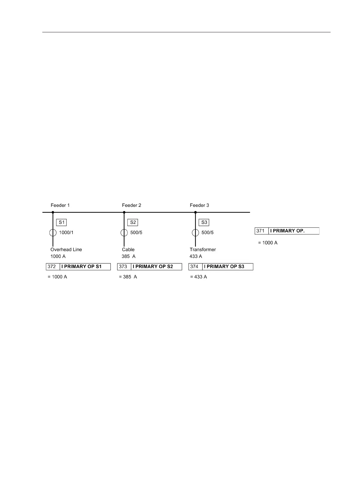
The feeders of a busbar may be rated for different currents. For instance, an overhead
line may be able to carry higher load than a cable feeder or a transformer feeder. You
can define a primary rated current for each side (feeder) of the protected object; this
current will be the reference for all referred values. These ratings may differ from the
rated currents of the associated current transformers which latter will be entered at a
later stage (current transformer data). Figure 2-12 shows the example of a busbar with
3 feeders.
Additionally, a rated current for the entire busbar as the main protected object can be
determined. The currents of all measuring locations assigned to the main object are
converted such that the values of the differential protection are referred to this rated
current of the main protected object, here the busbar. If the current rating of the busbar
is known, set this rated current in address 371 I PRIMARY OP.. If no rated current
of the busbar is defined, you should select the highest of the rated currents of the sides
(= feeders). In Figure 2-12, the rated object current (busbar current) would be 1000 A.
Figure 2-12 Rated current of the sides of a busbar with 3 feeders (set address 105 PROT. OBJECT = 3ph Busbar)
The object data concern only data of the protected main object as defined in the topol-
ogy. No data of the sides which are not assigned are requested here. They will be
entered at a later date (margin heading „Object Data for Further Protected Objects“).
Under address 372 I PRIMARY OP S1, set the rated primary current of the feeder
1. As mentioned above, the sides and the assigned measurement locations are iden-
tical for busbars.
The same considerations apply for the further sides:
• Address 373 I PRIMARY OP S2 for side (feeder) 2,
• Address 374 I PRIMARY OP S3 for side (feeder) 3,
• Address 375 I PRIMARY OP S4 for side (feeder) 4,
• Address 376 I PRIMARY OP S5 for side (feeder) 5.
Addresses 375 and 376, are omitted in 7UT613 and 7UT633 since these versions
allow only for 3 sides.
 Loading...


