Installation, Connection and Branch Layout
SIRIUS 3RW44 System Manual
GWA 4NEB 535 2195-02 DS 04
3-7
Notice
The DC braking and combined braking device functions are no longer available
for inside delta circuits.
In order to ensure proper functioning of the soft starter, the electric connection of
the main voltage (line and motor side) must be made according to the given
circuit examples (refer to Section Chapter 9.1 "Connection Examples for Main
and Control Circuits").
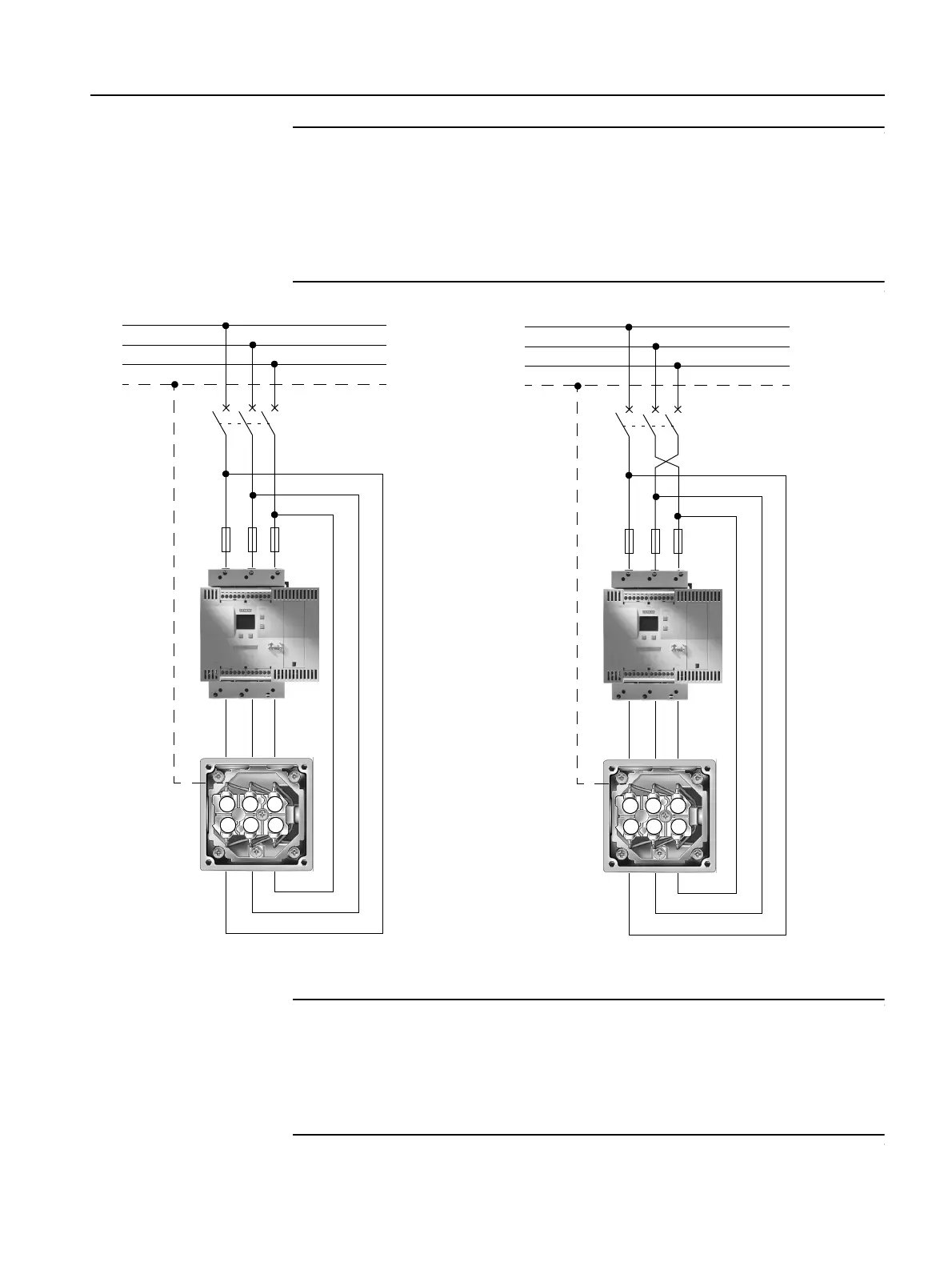
Figure 3-5:Block diagram of a 3RW44 soft starter in an inside delta circuit
Notice
If a main or line contactor is used, this contactor must not be connected between
the soft starter and the motor or in the return line between the motor and the soft
starter. Otherwise the soft starter would not recognize the current circuit version
(standard circuit or inside delta circuit) and would output the error message:
"Load phases 1-3 missing".
Motor rotation in phase direction Motor rotation counterclockwise to phase direction
U1 V1 W1
W2 U2 V2
M1
Q11
Q1
F3
3/N/PE~50 Hz 400 V
L1
L3
PE
L2
U1 V1 W1
W2 U2 V2
M1
Q11
Q1
F3
3/N/PE~50 Hz 400 V
L1
L3
PE
L2

 Loading...


