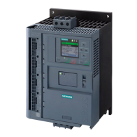
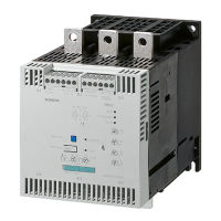
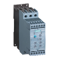
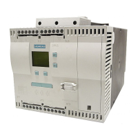
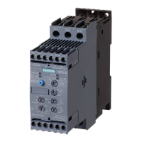
SIRIUS 3RW55 soft starter
Manual, 08/2018, A5E35630887002A/RS-AB/002
53
Overview of all connections
Main circuit connection network 1 / L1, 3 / L2, 5 / L3
Main circuit connection load (motor) 2 / T1, 4 / T2, 6 / T3
A1 / A2: Supply voltage for control terminals
Output 13, 14 (output 1): For signaling operating states and faults (parameterizable)
Output 23, 24 (output 2): For signaling operating states and faults (parameterizable)
Output 95, 96 and 98 (output 3): For signaling warnings and faults
Output 43, 44 (output 4): For signaling operating states and faults (parameterizable)
Analog output AQ-, AQ I+ and AQ U+: Connection of a measuring device to display the motor
current (optional)
• AQ- / AQ U+: For measuring devices with output signal type Voltage, signal range 0 ... 10 V
• AQ- / AQ I+: For measuring devices with output signal type Current, signal range
4 ... 20 mA
Control inputs DI1, DI2, DI3, DI4, L+ and M
Thermistor motor protection T1 and T2: Connection of a temperature sensor (optional)
Note
Parameterizing the analog output
You can parameterize the output of the analog output with the 3RW5 HMI High Feature.
141)

 Loading...


