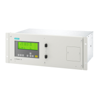
Gas path 19" rack unit
Piped (only possible
without pump)
Gas connections 6 mm / ¼" Stainless steel 1.4571
Pipes Stainless steel 1.4571
Analyzer chamber (only IR)
● Body
● Lining
● Nozzle
● Window
● Adhesive
● O-ring
Aluminum
Pure aluminum (not with UV module)
Stainless steel 1.4571
CaF
2
Epoxy resin-based adhesive
FKM
Bench-top unit (only
IR + optionally availa‐
ble with ec O2 ver‐
sions)
Condensation trap at gas inlet PA6 (polyamide)
Condensation trap PE (polyethylene)
3.5 Wiring diagrams
3.5.1 Gas ow diagram
Legend for the gas ow diagrams
1 Inlet for sample gas/calibration gas
2 Gas outlet
3 Inlet for AUTOCAL/zero gas or
inlet for sample gas/calibration gas (channel 2)
4 Gas outlet (channel 2)
5 Enclosure purging
6 Inlet of atmospheric pressure sensor
7 Inlet of chopper compartment purging
8 Condensation trap with lter
9 Fine safety lter
10 Solenoid valve
11 Sample gas pump
12 Pressure switch
13 Flow indicator
14 IR analyzer unit
15 Safety condensation trap
16 Oxygen sensor (electrochemical)
17 Atmospheric pressure sensor
18 Hydrogen sulde sensor
Description
3.5 Wiring diagrams
ULTRAMAT 23
Equipment Manual, 04/2022, A5E37100388-012 43

 Loading...


